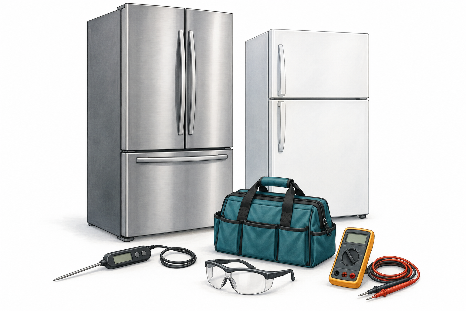
How to use this module
Refrigerator service brings several systems together: heat transfer, airflow, electrical controls, water delivery and the customer’s immediate need to protect food. A successful diagnosis explains how those systems interact and identifies the evidence needed before ordering parts.
Your learning outcomes
- Explain refrigerant state and heat flow through a vapor-compression system.
- Separate compressor, airflow, defrost, sensing and water-system symptoms.
- Interpret supplied readings using the correct model specifications and test conditions.
- Build a safe test sequence that can disprove the first diagnosis.
- Use brand information and service bulletins without treating them as proof of failure.
- Prepare a repair estimate, explain alternatives and document verification.
Learning route
| Units | Focus | Core time |
|---|---|---|
| 1.1–1.2 | Refrigeration and compressor reasoning | 2 hr 15 min |
| 1.3–1.4 | Defrost and airflow diagnosis | 2 hr |
| 1.5–1.6 | Controls, ice and water | 2 hr |
| 1.7–1.8 | Model research and customer decisions | 1 hr 15 min |
| Assessment | Written exam, three cases and review | 2 hr 30 min |
Core study estimate: 10 hours. Allow another 2–3 hours for optional practice and worksheet completion. These are planning estimates, not minimum certification hours.
What to have nearby
Use this workbook, Module 0, a calculator, a notebook, and the exact service information for any training appliance. Optional bench practice uses instructor-supplied disconnected parts and a suitable meter. All energized readings in the worked examples and assessments are supplied data; learners are not asked to take exposed live measurements.
How the learning activities work
The standard throughout this course
Start safely: intake and evidence
Set the boundary before opening anything
This module develops diagnostic reasoning. It does not establish electrical qualification, refrigerant certification or authorization to perform sealed-system work. Many refrigerator repairs concern air, controls or water and do not require opening the refrigerant circuit. Check the requirements for the actual work and refrigerant. [1, 2]
Protect the food and establish the timeline
FDA guidance calls for a refrigerator at 40°F (4°C) or below and a freezer at 0°F (−18°C). A display may show the setpoint rather than the measured temperature. Use an appropriate appliance thermometer, and direct questions about food that has warmed to FDA guidance; present temperature cannot reconstruct its storage history. [4]
- Ask when the symptom began, whether it is continuous, what changed, and whether power, doors, loading or settings were involved. Record prior repairs and any thawing or resets.
- Identify the complete model and serial number, refrigerant label, architecture, setpoints, ambient temperature and door-seal condition. Photograph relevant details with permission.
- Record both compartment temperatures, probe placement, elapsed time, door state and instrument. Instant air readings swing after openings and defrost; compare a trend under repeatable conditions.
- Protect the floor and water connections when moving the cabinet. Use the installation instructions for stability, leveling, clearances and restraints. Keep hands clear of fans, sharp fins and hot tubing.
When to stop
Stop for damaged power connections, water near energized parts, unstable handling, suspected refrigerant leakage or work outside your training. R-600a requires flammable-refrigerant procedures and suitable equipment. Do not operate possible ignition sources around a suspected release; follow the emergency and site safety procedure. [5]
The display reads 37°F, but a thermometer reads 48°F after the door has been open. What can you conclude?
1.1 Sealed system theory
Refrigeration moves heat from the cabinet into the room. The evaporator absorbs cabinet heat; the condenser releases that heat plus the energy added by compression. The compressor circulates refrigerant and maintains a pressure difference with the metering restriction.
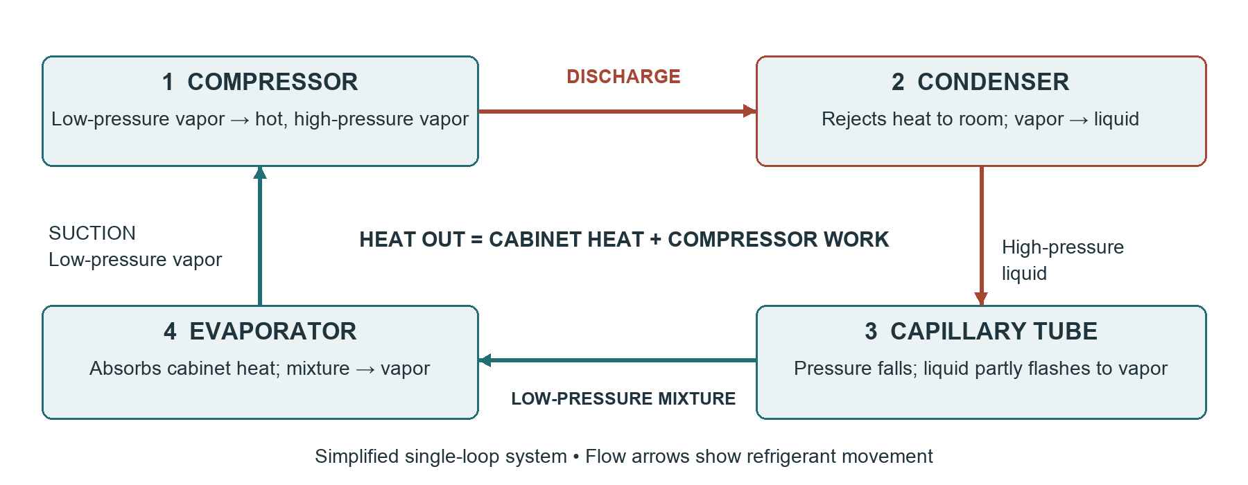
Follow the refrigerant, then follow the heat
- The compressor draws in low-pressure vapor and discharges hotter, higher-pressure vapor. It is intended to compress vapor, not a stream of liquid.
- In the condenser, refrigerant rejects heat and condenses. The condenser may be exposed tubing, a forced-air coil or tubing embedded in cabinet walls. Not every refrigerator has a condenser fan.
- A capillary tube provides a fixed restriction. As pressure falls, some liquid flashes into vapor. The evaporator receives a low-pressure mixture; the capillary is selected for that system.
- In the evaporator, the remaining liquid boils as it absorbs heat. Vapor returns through the suction line. Some designs add multiple evaporators and refrigerant-routing valves.
The filter-drier helps control moisture and contaminants. It is not an air filter and is not a routine homeowner replacement. Sealed-system service requires procedures beyond the theory in this unit. [6]
Why can a refrigerator warm the room while it cools food?
Refrigerants and pressure meaning
Read the label before choosing equipment
| Refrigerant | What the learner needs to know |
|---|---|
| R-134a | An HFC found in many existing refrigerators. Use the specified refrigerant, lubricant and procedures. It is not interchangeable with R-600a. |
| R-600a / isobutane | A flammable hydrocarbon. Small charge size does not remove ignition risk. Charge mass, component approvals and service equipment must match the appliance. |
| R-12 | An older CFC refrigerant. Do not assume R-134a is a drop-in substitute; any permitted retrofit needs an approved procedure and compatibility review. |
EPA generally prohibits intentional venting of covered refrigerants during service, with specified exceptions including R-600a in household refrigerators/freezers. That environmental exemption does not authorize unsafe release or remove fire precautions. Confirm the applicable requirements; use the manufacturer’s handling procedure and equipment rated for the refrigerant. Removing the charge alone is not proof that a system is safe for hot work. [1, 2, 5]
Saturation temperature is not cabinet temperature
For a pure refrigerant at liquid–vapor equilibrium, pressure corresponds to a saturation temperature. Superheated vapor and subcooled liquid are not necessarily at that temperature. Pressure readings also depend on load, ambient conditions, compressor speed, operating mode and where the measurement is taken.
| R-134a saturation temperature | Absolute pressure | Approx. gauge pressure |
|---|---|---|
| 0°F | 21.163 psia | 6.5 psig |
| 32°F | 42.486 psia | 27.8 psig |
| 100°F | 138.996 psia | 124.3 psig |
Values from Chemours, converted using 14.696 psi atmospheric pressure and rounded to 0.1 psig. These are property examples, not target operating pressures or charging instructions. Gauge pressure = absolute pressure − local atmospheric pressure. [7]
A useful distinction
A cold evaporator must be below the air temperature to absorb heat. A freezer at 0°F does not imply a 0°F refrigerant saturation temperature. Likewise, an equalized pressure reading cannot establish the correct charge mass. Do not add refrigerant simply to reach a generic pressure range.
At standard atmospheric pressure, 42.486 psia is how many psig?
Read the evaporator pattern
A frost pattern is a snapshot of heat transfer, moisture and operating history. Document it before thawing when safe access is possible. Isolate power before panel removal; do not run an exposed appliance merely to obtain a teaching image.
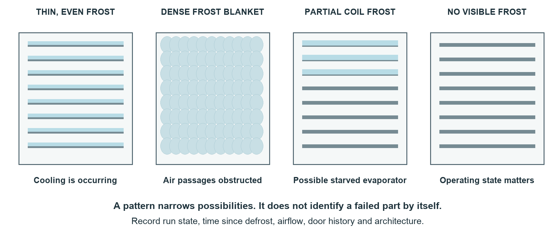
What each pattern can support
- Thin, distributed frost during cooling: refrigerant is absorbing heat over the observed area. This does not establish charge accuracy, full capacity or automatic defrost performance.
- Dense frost blocking fins: investigate defrost, air leakage, door history, sensor placement and airflow. Heavy frost alone does not identify a failed heater or board.
- Partial frost after an appropriate documented run condition: may support a starved evaporator. Low charge, restriction and operating-state effects remain possibilities; check routing on multi-evaporator systems.
- No visible frost: may occur after defrost, during an off period, on a warmer fresh-food evaporator or when cooling has failed. First establish whether that evaporator should currently be cooling.
Keep local ice separate from a whole-coil problem
A solid ice sheet in the drain trough or on the freezer floor suggests a drainage problem. Frost around a door or ice chute suggests moisture entry. Ice around a fan may result from either source and can damage the blade or motor. Record location, texture and extent rather than writing only “iced up.”
A coil is clear immediately after defrost. Is the refrigerant charge low?
Diagnose before opening the circuit
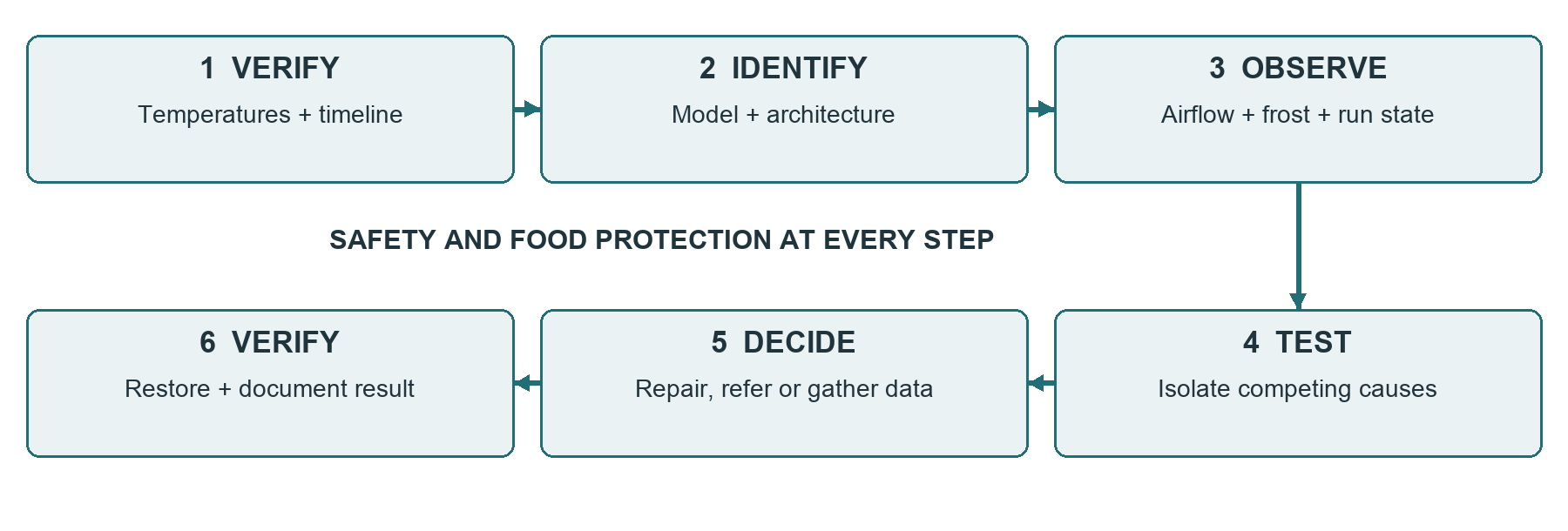
Non-invasive evidence first
Start with cabinet temperatures and their trend. Confirm the cooling request, compressor state, condenser heat rejection, evaporator airflow and any visible frost or drainage problem. Use appropriate temperature probes where safe access is permitted; touching hot tubing is not a measurement method.
Worked case: partial frost, both sections warm
Training data: a single-evaporator refrigerator has a persistent cooling request. Both fans operate, accessible air paths are clear, and a qualified technician documents adequate supply and compressor operation. After the specified run period, frost remains near the evaporator inlet and cabinet temperatures are not falling as expected.
Reasoning: the pattern and temperature trend justify further sealed-system evaluation, but they do not distinguish a leak from a restriction or poor pumping. Record the evidence and refer to a suitably trained sealed-system technician. Do not quote a compressor as confirmed or fit a piercing valve as a routine first test.
What the specialist handoff should contain
Provide identification, refrigerant and charge label, ambient and compartment readings, elapsed run time, operating mode, documented airflow and defrost checks, current/error information, photos, prior repairs and what remains uncertain. Explain to the customer whether the next step is diagnostic work or a confirmed repair. [6]
Why is “recharge and see” weak diagnosis?
1.2 Compressors and starting systems
Identify the motor and the drive separately
Reciprocating describes a piston mechanism; inverter describes how motor power is controlled. A reciprocating compressor may be variable-speed. Linear designs move the piston with a different drive arrangement. Brand name, cabinet age and the number of visible pins are not enough to select a test procedure.
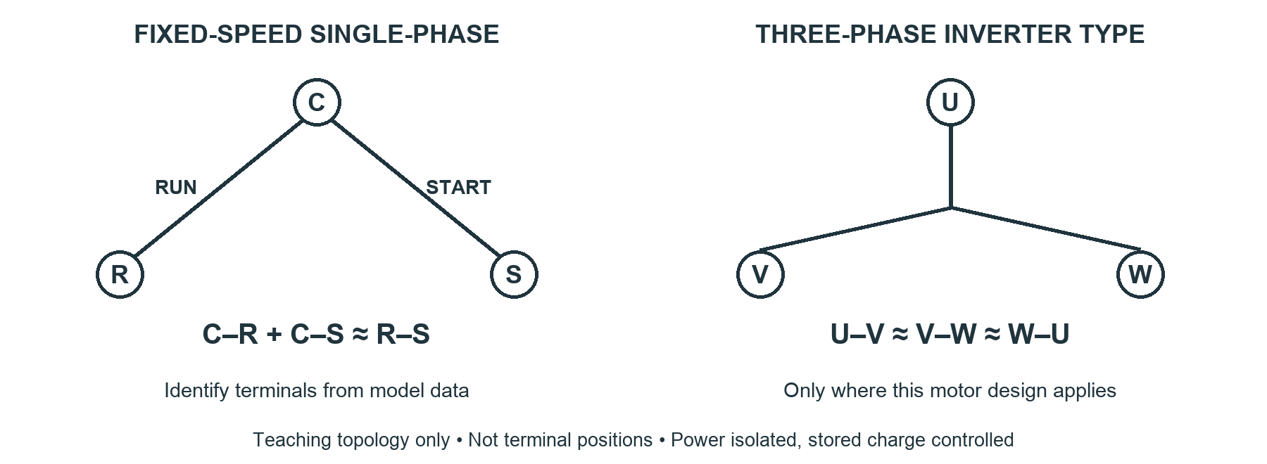
Fixed-speed starting equipment
A single-phase compressor may use a PTC starting device, a current relay and one or more capacitors, depending on its motor design. A PTC initially permits starting current and then increases resistance as it heats. The specified device, protector and capacitor combination matters; do not substitute a universal kit without explicit approval. [8]
Protect the terminals and the technician
Isolate power, control stored charge and follow the compressor manufacturer’s terminal-access instructions. Do not energize with damaged pins, insulation or terminal covers. Record the nameplate and original connections before disconnecting components. Do not attempt direct-power testing of an inverter-driven compressor.
A refrigerator has a piston compressor controlled by an inverter. Is it “reciprocating” or “inverter”?
Fixed-speed compressor reasoning
Read resistance as evidence, not a verdict
For a documented C–R–S single-phase motor, isolate the compressor from its starting components and other circuit paths. Identify terminals from the model diagram. Record temperature, meter lead resistance and measured values. A protector still open from overheating can change what is measurable.
| Supplied training reading | Interpretation |
|---|---|
| C–R = 3.0 Ω; C–S = 6.0 Ω; R–S = 9.0 Ω | The sum relationship is consistent with two connected windings. It does not prove that the compressor will start or pump. |
| One or more readings = OL | Recheck contact, range, terminal identity, temperature and protector location before concluding that a winding is open. |
| Measurable path from a terminal to the shell | Treat as a possible insulation fault. Keep isolated and follow the approved insulation-test procedure. |
| OL from terminals to shell on a multimeter | No path detected at that instrument’s test conditions. This is not a complete insulation test or proof of safe operation. |
Worked case: hum, click, repeat
Training data: a compressor attempts to start and then protection operates. Its cold winding resistances meet the supplied model limits. The technician has not yet verified supply during the attempt or checked the specified starting device.
Why a hard-start shortcut is inadequate
An extra capacitor is not a universal diagnostic tool. It can be incompatible with the motor or protective system and does not prove long-term reliability if the compressor happens to start. Never use it to test a suspected shell fault or an inverter/linear compressor. Follow an explicitly approved procedure or escalate.
The three winding readings add correctly. What statement belongs on the work order?
Inverter and linear compressor diagnosis
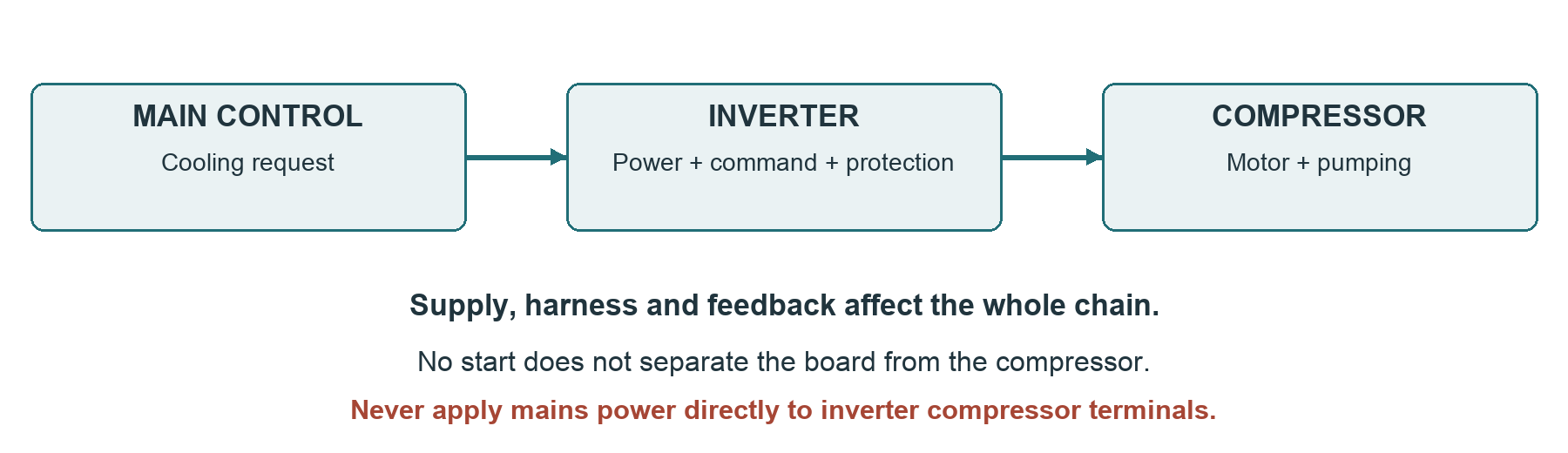
Separate the questions
- Is cooling actually requested? Check setpoints, sensor evidence, operating mode, defrost state and startup delays. A silent compressor can be normal at that moment.
- Is the drive receiving the required supply and valid command? Qualified measurements must use the specified points, signal method and operating state. A generic meter value may not establish a valid communication signal.
- Are connectors and harnesses intact? Inspect only after isolation and stored-energy control. A damaged harness can interrupt power, command or feedback.
- Does the compressor pass the model’s isolated checks? Balanced pair readings apply only where the motor design calls for them. Use specified resistance and insulation limits, not a universal percentage.
- What does the manufacturer’s fault sequence require next? Some tests need a service tool. Escalate when the necessary method is unavailable instead of swapping the cheaper board as a diagnosis.
Worked example: ambiguous no-start
Training data: the control requests cooling, a drive reports a motor fault, and isolated phase-pair readings are similar. A damaged compressor harness connector is then found. The code and resistance results do not justify replacing either major component yet. Correct the confirmed connection defect using the approved repair method and repeat the full diagnostic sequence.
Replacement includes compatibility
Verify the exact compressor and drive pairing, refrigerant, approved substitution, firmware or programming requirement and warranty authorization. A physically fitting replacement can still be wrong. Normal operation after a board change requires the original complaint to be retested, not merely a display that lights up.
Why should an ordinary AC-voltage reading at inverter output not be treated as a universal pass/fail test?
1.3 Defrost systems and drainage
A cold evaporator collects moisture from circulating air. On frost-free designs, periodic defrost removes that accumulation before it blocks heat transfer and airflow. A defrost problem can first appear as a warm fresh-food section, weak airflow or a fan contacting ice.
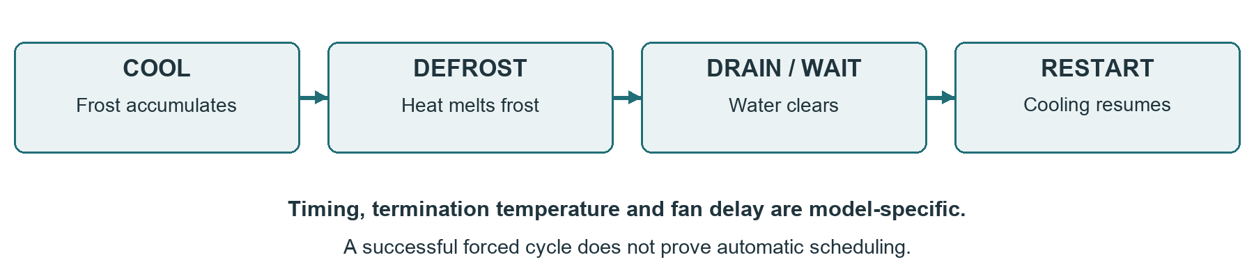
Three common control arrangements
| Arrangement | How it works | Diagnostic caution |
|---|---|---|
| Mechanical timer | A motor and cam switch between cooling and defrost on a defined schedule. | A manual advance proves only what happens in that test state. Contacts, timer motor and heater path remain separate questions. |
| Adaptive defrost control | A dedicated electronic control adjusts scheduling using operating history and available inputs. | Inputs, wiring and heater protection must be checked before condemning the control. |
| Main control with sensors | The main board manages defrost using model-specific logic, sensor feedback and limits. | A plausible sensor reading can still be wrong. A code may identify an open/short condition without detecting drift. |
These arrangements overlap across product generations. Do not assign a design from a production year alone. A temperature limiter or thermal fuse can remain in the heater path even when a board uses a thermistor for normal termination.
A stalled defrost state
Cooling may remain off if a timer or control stays in defrost, but that does not mean the heater must remain powered continuously. The heater may already be interrupted by its temperature limit or safety device. Diagnose the actual circuit rather than inferring heater operation from a warm cabinet.
A timer is manually advanced and the heater operates. Is the timer proven faulty?
Trace the defrost circuit
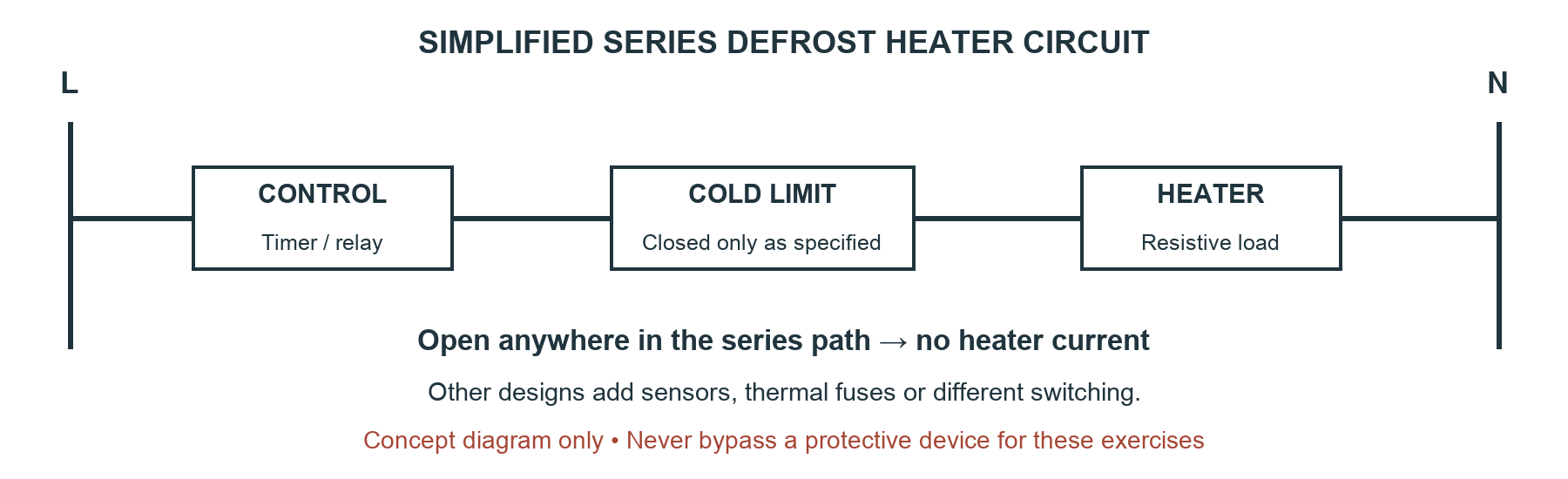
Test the right component in the right state
- Heater: with power isolated and charge controlled, disconnect as required to remove parallel paths. Compare resistance with the exact specification. Confirm an OL result with good probe contact and a proven meter. Heater construction does not set one universal resistance range.
- Bimetal terminator: compare its open/closed state with actual sensor temperature and the specified opening and closing points. A 32°F ice bath may be too warm to close a particular limiter. Never condemn it merely because it is open at room temperature.
- Thermal fuse: a one-shot device is different from a resetting bimetal. Use the circuit legend, exact part and specified test; investigate the reason for overheating before replacement.
- Thermistor: compare isolated resistance with its model resistance/temperature table. Check mounting, thermal contact and harness condition as well as the sensing element.
Worked electrical example
Fictional specification: a heater is rated 120 V, 400 W for a simple resistive-load calculation. Expected operating resistance is approximately V²/P = 120²/400 = 36 Ω. Expected current is P/V = 3.33 A. A supplied 36.5 Ω cold reading is only a reasonableness check; the actual acceptance limit must come from the part specification and test temperature.
Supplied qualified-test data show no heater current during a confirmed defrost request. That is consistent with an open anywhere in the series path or missing supply. It does not identify which item is open. Choose isolated component and harness checks before a board conclusion.
Why must the limiter temperature be written beside a continuity reading?
A disciplined frost-up investigation
Preserve evidence before thawing
- Confirm the complaint and protect food. Record both compartment temperatures, door history and time since any manual thaw or reset.
- Identify the architecture. A dual-evaporator appliance may have a fault confined to one compartment. Locate the correct sensor, heater and drain in the model information.
- Document the frost location and coverage after safe isolation and access. Look for door leakage, blocked vents, misplaced covers, drain ice and fan contact.
- Record relevant cold-state tests before thawing where the approved procedure permits. Thawing can change a limiter state and erase the original pattern.
- Thaw by the approved method while protecting the floor and electrics. Do not use a heat gun, hair dryer, sharp tool or improvised heater. Samsung specifically warns against hair dryers. [9]
- Test the heater, protection devices, sensors and wiring using exact conditions. Record measured values and the specification, not simply “checks good.”
- Use the model service procedure if a forced test is justified and within qualification. Record the selected test, observed response and termination; restore normal mode afterward.
What a forced cycle proves—and what it does not
A heater operating during a forced test supports operation of the tested path at that time. It does not establish automatic scheduling, sensor calibration, drainage, complete frost removal or the absence of an intermittent fault.
Worked case: the warm limiter trap
Training data: the learner fully thaws a refrigerator, then measures an open defrost limiter at 72°F. The supplied specification says it opens above 50°F and closes below 15°F. The open result is expected. An ice-water bath near 32°F does not reach the specified closing temperature. Use the approved cold-state method and keep connectors dry; do not bypass the limiter.
The coil frosts up again after a complete thaw. What did the thaw establish?
Drainage and a complete defrost repair
Trace meltwater all the way out
Meltwater should reach the collection trough, pass through the drain and reach the intended pan. A blocked or frozen drain can let water pool, refreeze and eventually leak onto the floor. A local drain ice mass is different evidence from a blanket covering the evaporator fins.
Repair sequence
- Use the approved access and clearing method. Protect tubing, wiring, insulation and plastic liners. Do not chip ice from the evaporator or push an unknown tool deep into a drain.
- Confirm the drain path with the manufacturer’s method and a controlled amount of water where specified. Watch for leakage and proper delivery to the pan; water disappearing from the trough is incomplete proof.
- Check the pan position, drain outlet, cover seals, fan clearance and reinstalled insulation. A displaced evaporator cover can change airflow and cause a callback.
- Install a revised drain part or heater kit only after confirming the bulletin, model range, serial applicability and current part revision. Do not improvise a metal heat-transfer clip.
- Restore the appliance and verify cooling, airflow and drainage to the extent the visit permits. State any automatic defrost or long-term temperature check still outstanding.
Worked case: floor ice and a normal heater
Training data: the freezer floor has a clear ice sheet. The evaporator fins show only light frost; isolated heater and limiter checks meet the supplied specification. A controlled drain check backs up at the trough.
Reasoning: the drainage evidence is stronger than the hypothesis of a failed heater. Clear and inspect the specified drain path, determine the cause, and verify delivery to the pan. Continue investigating if the coil itself later shows abnormal accumulation; two faults can coexist.
Write a defensible completion note
“Cleared confirmed drain obstruction and corrected the displaced outlet under the model procedure. Test water reached the pan without leakage. Covers and seals restored; airflow present and cabinet temperature falling during the recorded observation period. Full automatic defrost recurrence check remains pending.”
A replacement heater melts ice, but water leaks onto the floor. Is the repair complete?
1.4 Airflow and fan systems
Identify the air paths before interpreting compartment temperatures. Many refrigerators use forced air, but static-cooling designs also exist. For a forced-air system, the supply and return paths must both remain open; a running fan cannot overcome every obstruction.
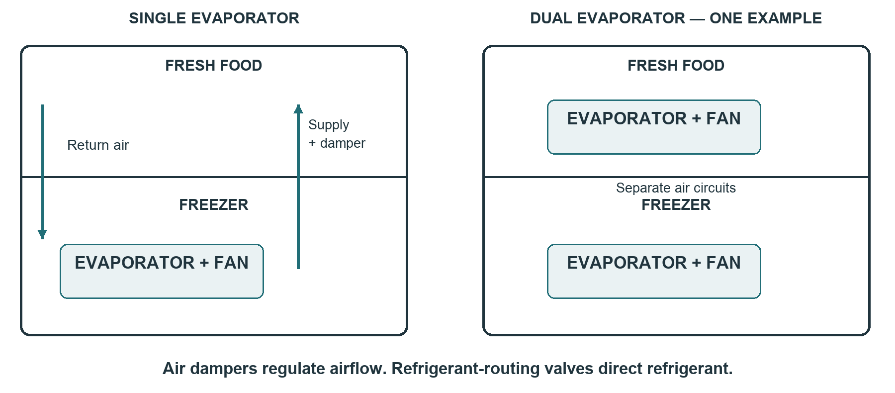
Single evaporator
One evaporator commonly serves the freezer and fresh-food section through ducts and a damper. A warm fresh-food section with a genuinely cold freezer directs attention to supply air, return air, fan output, damper operation and sensing. It does not prove a failed damper. Which sensor controls the compressor depends on the design.
Dual evaporator
Each section has its own cooling surface and usually its own fan. Some systems use a refrigerant-routing valve; others have different circuit arrangements. Follow the model diagram. A warm fresh-food compartment may involve its local fan, defrost, sensor or refrigerant path even when the freezer performs well.
Do not confuse three different parts
An air damper meters cabinet airflow. A refrigerant-routing valve changes refrigerant flow and may require sealed-system service. A mullion is a cabinet or door-divider structure; it is not automatically an air damper. Correct names help you find the correct diagram and replacement.
The freezer holds its target, but the fresh-food section is warm. What must you identify first?
Fans, dampers and heat rejection
Observe under a valid operating condition
A fan may stop when a door opens, during defrost, during a delay or when cooling is satisfied. Absence of sound at an open door is not a failure diagnosis. Use the manufacturer’s service procedure; do not improvise door-switch bypasses or reach toward a moving blade.
| Component | Evidence to collect | Before replacement |
|---|---|---|
| AC fan motor | Correct commanded state, mechanical clearance and specified supply at named terminals. | Confirm wiring, blade fit and obstruction. A loose blade can turn poorly while the motor runs. |
| Electronic / BLDC fan | Specified power, reference, command and any feedback signal; harness condition. | Supply voltage alone may not command operation. Signals and pin assignments vary. |
| Motorized air damper | Commanded position, actual flap travel and resulting airflow. | Check ice, linkage and both air paths. Motion during a service test does not prove normal sensor-driven control. |
| Condenser and its fan, if fitted | Clearance, accessible dirt loading, fan response and heat-rejection trend. | Follow cleaning/access instructions; some condensers are concealed or not user-serviceable. |
A sound is a clue
A scraping sound that stops when the fan is commanded off can locate the source near the fan. Inspect blade clearance, ice and mounting after isolation. Do not assume the motor is faulty because it was noisy. A gurgle, click or variable-speed change may be normal on one model and abnormal on another.
Heat rejection completes the loop
Restricted condenser airflow can reduce cooling capacity and increase thermal stress. Correct the confirmed restriction promptly and check operating results. Do not promise that a compressor will fail within a fixed number of days or weeks; that cannot be inferred from a warm coil alone.
Supplied data show the correct fan supply but no rotation. Is that enough for an electronic fan?
Airflow cases and temperature trends
Worked case A: the hidden return blockage
Training data: a single-evaporator refrigerator holds the freezer near its target, but fresh-food readings remain high. The fan runs and the damper opens in a valid service test. Food packages cover the lower return opening.
Worked case B: the misleading “cold freezer”
The customer says the freezer is fine because food is still hard. Supplied readings show 18°F in the freezer and 48°F in fresh food after an appropriate observation period. The freezer is also warmer than intended. Reclassify the complaint as a whole-system performance issue and investigate cooling demand, defrost, airflow, heat rejection and compressor evidence.
Measure changes consistently
- Use the same probe position for before/after comparison. Label readings as air, simulated food load, food package or surface temperature. They are not interchangeable.
- Record room temperature, setpoints, door openings, cabinet loading, elapsed time and any service-mode intervention.
- Allow the stabilization interval in the manufacturer’s instructions. A short falling trend supports recovery but does not demonstrate final equilibrium or performance through defrost.
- Reinstall covers before normal performance evaluation. Covers often form essential air ducts; an uncovered evaporator changes the system being tested.
Practice: choose the next useful check
Training data: fresh food is too cold. The damper moves in service mode, but during normal operation the control keeps requesting more cooling even when a reference thermometer shows a cold compartment. Which evidence separates a sensing problem from a damper problem?
Check your reasoning. Compare actual temperature with the sensor’s indicated value or isolated model-specific resistance. Check sensor mounting and harness integrity. A control receiving a falsely warm input may be commanding the damper correctly for the information it sees.
Customer teaching that prevents callbacks
Show the actual vent locations and the model’s loading clearances. Explain that setpoint changes need time to take effect. Record the chosen settings and the follow-up condition rather than telling the customer to keep making the setting colder.
1.5 Sensors, controls and communication
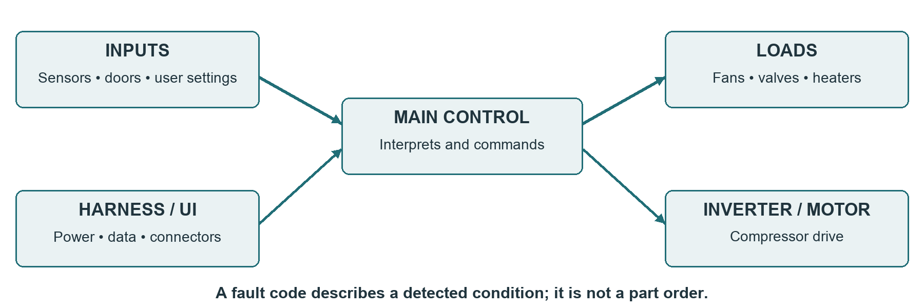
Inputs explain outputs
A control board responds to sensor readings, door state, settings, timers and communication. When an output looks wrong, first ask what input or prerequisite could make that behavior reasonable. A defrost delay, a bin-full signal or a satisfied cooling demand may intentionally stop a load.
The thermostat is a switch; the thermistor is a sensor
A mechanical thermostat switches contacts according to its sensing element, setting and differential. Its required open/closed state depends on the specified temperature and position. Do not assume an ice bath must open every refrigerator thermostat. Do not damage or sharply bend a capillary sensing element.
A thermistor changes resistance with temperature. The board interprets that resistance through its input circuit. Cabinet, evaporator, ice-box and ambient sensors can have different jobs and different specifications. Their physical placement is part of the measurement system.
Common diagnostic traps
- A normal-looking board can fail; a visibly damaged board still requires investigation of the cause and connected loads.
- An unlit display can result from lost power or a harness fault. It is not proof of a failed main board.
- A power reset that temporarily restores operation is an observation. It does not identify firmware corruption or complete a repair.
The control reports a warm fresh-food sensor and holds the damper open. What is the next question?
Test a sensor at a known temperature
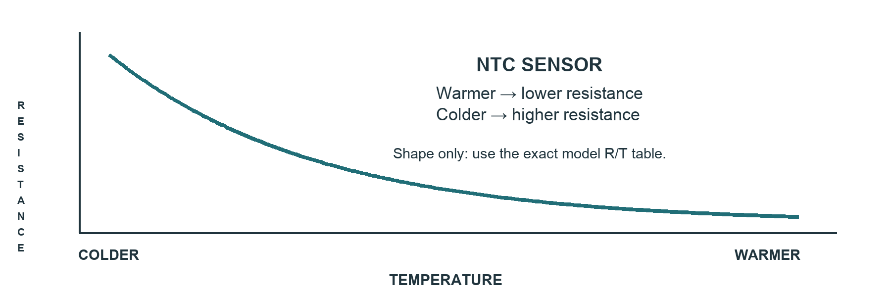
A reliable resistance/temperature comparison
- Identify the exact sensor and obtain its resistance/temperature table, tolerance and test method. Confirm that the table applies to the part revision.
- Isolate power and disconnect the sensor as specified. A reading through board circuitry may not represent the sensor alone. Keep connectors and unsealed parts dry.
- Let the sensing element stabilize at a measured temperature using an approved method. Record the reference thermometer and allow for its accuracy.
- Measure resistance, compare with the correct limit, and repeat at a second specified point when required. A single plausible value does not establish the whole response curve.
- Check the harness and sensor mounting. Compare at the sensor and board connector where the isolated test procedure permits; a difference can expose a wiring problem.
Worked example: an open/short test can miss drift
Fictional sensor specification: 10.0 kΩ ±5% at 77°F. Acceptable range is 9.5–10.5 kΩ. After stabilization, the disconnected sensor reads 12.8 kΩ. The harness adds negligible resistance in separate checks. That supports an out-of-specification sensor at the measured temperature; an open/short screening test could still call it “pass.”
Before ordering, verify the sensor identity, thermometer, thermal stabilization and meter setup. Refit the approved sensor in the correct clip or pocket; moving it to a convenient location changes the temperature it senses.
A disconnected sensor meets its limit, but the board-end reading does not. What becomes more likely?
Service mode and board decisions
Treat service mode as a controlled experiment
Obtain the exact entry, prerequisites, test sequence and exit instructions before starting. Identify which loads can run, whether tests are timed and what each displayed number means. A test number, command status and measured result are different information.
Manufacturer reading exercise
Whirlpool tech sheet W11394619A illustrates why exact documentation matters: its sensor tests report pass/open/short states; separate tests operate fans, airflow baffles and refrigerant routing. These are distinct functions. Read the sheet as a reference exercise only—it is not a procedure for every Whirlpool refrigerator. [10]
Before a board conclusion
- Verify power and the relevant grounds/references using the specified safe method. Rule out a supply problem before interpreting missing outputs.
- Confirm the input values, operating state and command prerequisites. Verify the load and harness with the approved tests.
- Inspect de-energized connectors for pin damage, moisture or poor engagement. Investigate door-hinge wiring when symptoms change with door movement.
- Use the prescribed signal test or service tool when communication is involved. A continuity test alone cannot prove reliable data transfer under operation.
- Confirm the replacement revision and any programming or pairing requirement. Do not replace the least expensive board first simply because the diagnosis is uncertain.
Worked case: intermittent display
Training data: display loss coincides with door movement; cooling sometimes continues. Isolated inspection finds a damaged conductor near the hinge. A repeatable harness fault is stronger evidence than the assumption that a dead display means a dead board. Repair or replace the harness as approved, restore strain relief, then verify stable operation through normal door movement.
After a fan runs in service mode, can you mark all fan control functions as good?
1.6 Ice makers and water systems
Separate “not making ice” from “not dispensing ice.” A full bin with a silent dispenser is a different problem from an empty mold. Begin by describing what is present: water, frozen cubes, harvested cubes, a blocked chute or an incomplete cycle.
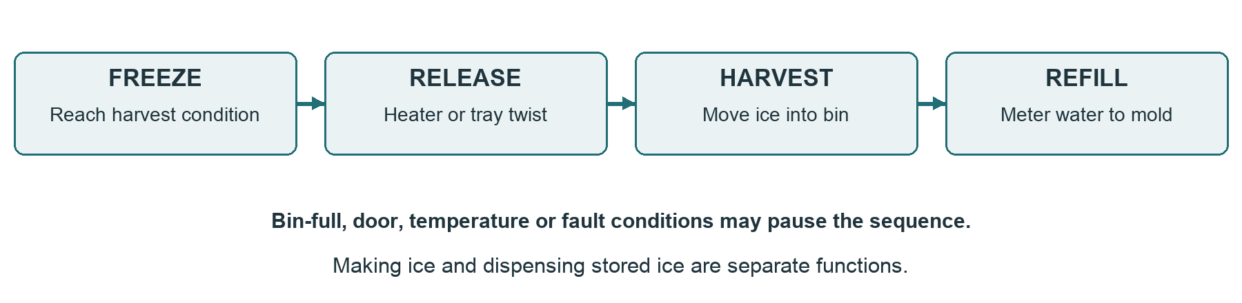
Recognize the design
A conventional modular ice maker may combine the mold, heater, thermostat, motor and mechanism. The inlet valve is usually a separate appliance component. Electronic and twist-tray designs use different sensing and harvest arrangements; do not apply one module’s jump-test procedure to another.
Production prerequisites
- Ice maker enabled, bin correctly installed and bin-full sensing satisfied.
- Door and other interlocks in the required state; no active fault blocking operation.
- Mold or compartment temperature low enough under the model’s criteria. A freezer setpoint alone is not evidence of mold temperature.
- Water supply available through the correct path, with the specified pressure/flow and no frozen fill tube.
- Mechanism clear and correctly positioned, with no ice obstruction or failed release function.
A bin is full but no ice exits the dispenser. Should the ice-making module be replaced first?
Trace the water path
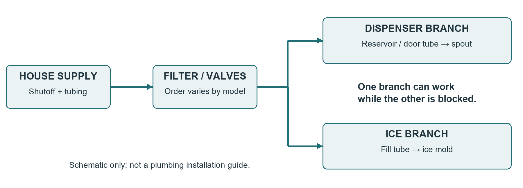
From the house connection to the outlet
Follow the model routing diagram. A refrigerator may have an isolation valve, filter head, reservoir, branch valves and separate tubing runs in a different order from the teaching figure. Some have no chilled reservoir. Identify each branch before disconnecting anything.
Filter questions that save time
- Did the problem begin after a filter change? Check the correct part, orientation, seating and any required recognition procedure.
- Does the design use an automatic bypass or a separate approved bypass plug? Do not assume removing a filter restores flow on every model.
- Does the manufacturer permit a bypass comparison? If so, record the result using the same measured flow method; do not guess from sound.
- After installation, purge according to the owner’s instructions and inspect for leakage. Resetting the filter reminder does not restore a restricted filter.
GE’s dispenser guidance provides one model-family example: on applicable designs, improved flow with the specified bypass supports a restricted filter. It also identifies a frozen reservoir and installation problems as possibilities. Use the applicable instructions rather than transferring the procedure to another design. [11]
The ice maker fills but the dispenser does not. What can you infer?
Ice complaints: locate the failed stage
| Observation | Competing explanations | Next discriminating evidence |
|---|---|---|
| Mold stays empty | No fill command, supply restriction, valve fault or frozen fill tube. | Confirm cycle state; trace supply and the commanded fill path using model tests. |
| Water sits unfrozen | Insufficient local cooling, too much fill or recent refill. | Record mold/ice-box temperature and time; verify cooling and fill quantity. |
| Ice stays in mold | No harvest request, failed release, obstruction or mechanism fault. | Check prerequisites and observe the approved harvest test with guards in place. |
| Ice reaches bin but not glass | Bin coupling, auger, chute, door input or dispenser control. | Inspect isolated mechanism and compare command with the specified response. |
| Ice clumps or box frosts | Moisture entry, poor sealing, melt/refreeze or local cooling problem. | Inspect seals, chute closure, air path and local temperature history. |
Avoid destructive testing
Do not force an ice-bound bin, bypass protective devices, jumper unknown terminals or repeatedly trigger fill into a full mold. Obtain the exact service sequence first. A stalled harvest can leave a mechanism in an intermediate position; follow recovery instructions before the next test.
Worked case: frozen fill tube
Training data: harvest completes, but no water reaches the mold; inspection finds a frozen fill tube. Thawing restores one fill. Investigate why it froze: seepage through the valve, local overcooling, tube position, an applicable heater fault or other model-specific cause. One successful fill after thawing is not enough to call the valve or heater good.
A meaningful ice-maker completion check
Document successful harvest, correct fill without overflow, leak checks and required reset or initialization. Full ice production may take longer than the visit. State the remaining observation period from the manufacturer’s instructions and give the customer a specific follow-up condition.
A motor sounds active but ice remains in the mold. Does that prove the mold heater failed?
Water complaints and freezing
Frozen water is a symptom to explain
A fresh-food reservoir is intended to chill water without freezing it. Low use can contribute on some designs, but normal operation should not rely on continuous flow. Investigate temperature settings, control accuracy, loading, air routing, insulation and the model’s specific guidance. A frozen tube can split and leak after thawing.
Worked case: slow flow after a filter change
Training data: the dispenser filled 250 mL in 10 seconds before a filter change. It now fills 90 mL in the same interval. The supply valve is unchanged, tubing is not kinked and there are no visible leaks. An approved bypass comparison restores 250 mL in 10 seconds.
Worked case: water continues after the command ends
Training data: flow continues after the dispenser request stops. Shut off the water promptly and manage the leak risk. Possible causes include a mechanically leaking valve or an electrical/control condition holding it open. Qualified testing under the service procedure distinguishes command from mechanical closure. Do not leave the water supply on with an unresolved uncontrolled-flow condition.
Water service completion checklist
- All disturbed fittings secure, dry and checked under restored pressure; no hidden drip at the filter head or reservoir.
- Supply line not kinked, stretched, crushed or rubbing after the cabinet returns to position.
- Correct fill quantity, shutoff and timed dispenser flow under documented conditions.
- Any freeze cause corrected and thawed sections inspected for damage; seals and insulation restored.
- Customer knows the filter/flush instructions and any required follow-up. Avoid guaranteeing future output from a single short test.
A frozen reservoir thaws and dispensing returns. What remains?
1.7 Brand and model research
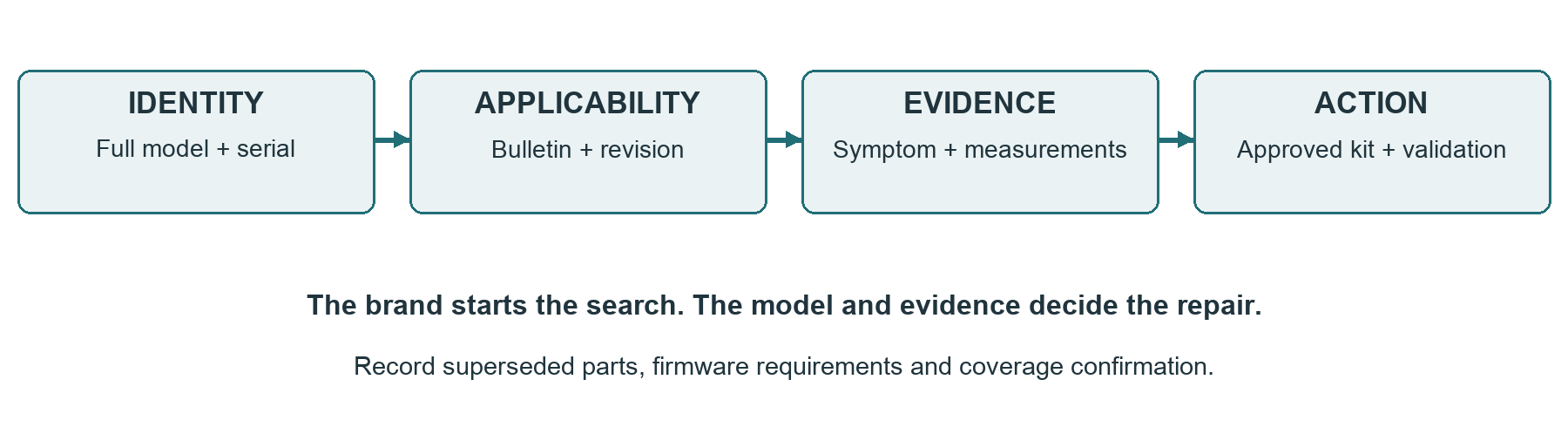
Brand familiarity can suggest where to look, but it cannot establish a failure rate or a diagnosis. This reference replaces broad “this brand always fails here” rules with a research path you can use on an actual service call.
| Manufacturer group | Research focus for the actual appliance |
|---|---|
| Samsung | Identify the exact cooling and ice-box design. For frost complaints, inspect moisture entry, drainage and relevant current service guidance before selecting a kit. |
| LG / LG-built products | Identify compressor and drive type, approved replacement pairing and any programming requirements. Verify model-specific warranty coverage before quoting. |
| Whirlpool / KitchenAid / Maytag | Confirm architecture and tech-sheet revision. Distinguish air baffles, refrigerant-routing valves, fans and defrost functions. Shared ownership does not mean identical circuits. |
| GE Appliances | Use exact model support and service data. Check sensor specifications, water-filter recognition, reservoir design and harness routing where relevant. |
| Frigidaire / Electrolux | Use the model’s motor, defrost, ice and valve documentation. Confirm part revisions and diagnostic prerequisites before transferring a pattern from another model. |
What belongs in a brand note
Record the precise symptom, model/serial range, source date, bulletin identifier, confirming test and approved correction. Distinguish a manufacturer bulletin from a shop observation. Neither a brand label nor an online anecdote is a replacement for the test result.
A colleague says a certain brand usually needs an inverter board. What should that change?
Service bulletins, parts and coverage
A five-field bulletin check
- Identity: match every relevant model suffix and serial/manufacturing range. Similar-looking cabinets may use different systems.
- Revision: record bulletin number, issue date and superseding revision. Confirm that an older kit has not been replaced.
- Trigger: compare the described symptom and conditions with the actual evidence. A bulletin about drain ice may not explain a whole-coil frost blanket.
- Correction: verify the full part list, installation conditions, firmware/programming and required post-repair checks. A partial kit may not accomplish the stated correction.
- Coverage: confirm who authorizes the work and which charges are covered. A service bulletin is not automatically a recall or free-repair promise.
Warranty is part of diagnosis planning
Check the original purchase date, exact model/serial, relevant warranty document and any authorized-service requirement before a major quote. Compressor parts coverage, labor coverage and sealed-system coverage can differ. Manufacturer confirmation controls the customer’s actual eligibility; do not infer an active settlement remedy from brand or age. LG’s support materials illustrate the need for product identification and warranty validation. [12]
Worked research example
Fictional bulletin: “SB-TRAIN-17 Rev C” applies to model T-240 suffix B, serial range 10000–19999, with water backing up at a specified drain outlet. The customer owns suffix A and has frost around an ice chute. The proposed drain kit is not supported by that bulletin. Search the correct documentation and diagnose the moisture-entry path.
Build your own useful pattern log
For each confirmed repair, record architecture, exact failure evidence, part revision, date and callback outcome. Separate “suspected” from “confirmed.” A pattern based on a few calls can guide attention but cannot support a public percentage or claim that every unit will fail.
The manufacturer covers a compressor part but not labor. What goes on the estimate?
1.8 Repair versus replacement
Present the evidence and the options before requesting repair authorization. A good recommendation reflects the confirmed fault, the full cost, the customer’s needs and any remaining uncertainty. Age or a fixed percentage alone cannot decide every refrigerator repair.
Compare like with like
| Repair side | Replacement side |
|---|---|
| Confirmed parts, labor, diagnostic fee, supplies and applicable taxes. State any diagnostic-fee credit. | Comparable delivered unit, installation, haul-away, required connection work and applicable taxes. |
| Written parts/labor coverage, exclusions, availability and expected downtime. | Fit, door clearance, utility connections, delivery timing and warranty terms. |
| Remaining condition: cabinet, door seals, corrosion, prior failures and other unresolved faults. | Any space modifications, panel matching, accessibility needs and differences in usable capacity. |
| What this repair restores, what remains uncertain and how success will be verified. | Whether a suitable replacement is actually available within the customer’s budget and timeline. |
Use a ratio as context
Repair ratio = complete repair estimate ÷ complete comparable replacement cost × 100. A 50% threshold can be a discussion prompt, but it is not a rule that proves replacement is better. A fitted built-in, a pending remodel, warranty coverage or a long delivery delay can change the decision. Avoid unsupported lifespan promises or brand-wide reliability claims.
Customer conversation sequence
- State the confirmed problem and the evidence. Separate a confirmed repair from a proposal for further diagnosis.
- Give the complete repair price, scope, exclusions and written warranty terms. Include realistic availability and downtime.
- Present a comparable replacement cost and any assumptions that still need a current quote.
- Explain your recommendation and uncertainty in ordinary language. Ask about fit, budget, timing and the customer’s priorities.
- Record the authorized choice and how the appliance and food will be managed while the work is pending.
When deferral is reasonable
A customer may defer a nonessential ice-maker repair if cooling and safe containment are verified and any leaking water branch is managed by an approved method. Deferral is not appropriate advice for uncontrolled water flow, an electrical hazard or food held at unsafe temperatures. State the actual use restrictions, not a blanket “still usable.”
A transparent estimate and handoff
Worked decision example
Fictional training figures, before tax: a confirmed repair needs a $140 part, two labor hours at $120/hour and $20 supplies. A $90 diagnostic fee already paid is fully credited toward the $400 repair total. The customer would pay $310 more. A comparable replacement is $1,450 plus $100 delivery/installation and $50 haul-away: $1,600 total.
The repair ratio is $400 ÷ $1,600 = 25%. The additional payment is not the full repair cost, and the $90 fee must not be counted twice. With no other known defect, repair may be reasonable, but discuss condition, coverage, timing and the customer’s priorities before recommending it.
A customer explanation you can adapt
“The test confirmed the failed component, and the related checks did not show another fault in that circuit. The complete repair is $400 before tax, including credit for the $90 diagnostic fee you paid, so the remaining amount is $310. A comparable installed replacement in this example is $1,600. Repair looks reasonable on the evidence we have. I will verify the cooling response after the work and explain any longer check that remains.”
Verify the original complaint
- Restore covers, air seals, insulation, protective devices, grounding, harness clips and water connections. Confirm required clearances and safe cabinet placement.
- Exit service mode and restore agreed settings. Check for new codes, water leakage, fan contact and abnormal operation.
- Record test duration, temperatures, conditions and the specific function restored. “Compressor running” does not prove food-storage temperature or automatic defrost performance.
- When full stabilization or ice production extends beyond the visit, state the manufacturer’s expected observation period and arrange a definite follow-up plan.
- Provide the itemized work order, authorization, actual written warranty and receipt. Do not invent a warranty duration or promise that unrelated old parts will not fail.
A $600 repair is compared with a $1,000 shelf price for a new unit that needs $250 of delivery and installation. Which denominator belongs in the ratio?
Assessment instructions
Part A: written examination
Answer all 40 questions without consulting the answer key. Select the single best answer for multiple-choice items. Each correct answer earns one point. Passing requires at least 32/40 (80%). The questions cover all eight units equally.
Part B: three diagnostic cases
Each case supplies a fictional model, conditions and training prices. These values apply only to the case. Use the case-response worksheet or a separate sheet. For every case, submit:
- A concise problem statement and at least three plausible causes at the initial-observation stage.
- A safe, ordered test plan and an explanation of which result separates the causes. Use supplied energized readings; do not perform live tests.
- A conclusion justified by the follow-up evidence, including what has not yet been established.
- An itemized pre-tax estimate using the supplied figures, labor allowance and any stated diagnostic-fee treatment. Do not quote an unconfirmed part as required.
- A short customer explanation covering repair versus replacement, the verified outcome needed and any follow-up.
Scoring rubric: 15 points per case
| Dimension | 3 points | 1–2 points | 0 points |
|---|---|---|---|
| Problem and causes | Accurate scope; plausible alternatives. | Some useful causes; important gap. | Unsupported part guess. |
| Safety and test plan | Safe sequence; discriminating tests. | Useful but incomplete sequence. | Unsafe or irrelevant plan. |
| Evidence and conclusion | Result supports claim; limits stated. | Direction sound; overclaim or gap. | Contradicts evidence. |
| Estimate | Correct scope, labor and total. | Minor omission or arithmetic error. | Wrong scope or no estimate. |
| Customer and verification | Clear options and meaningful checks. | Partial explanation or vague check. | Pressure, false certainty or no check. |
Case total: 45 points. Passing requires at least 36/45 (80%). Any unsafe proposed action must be corrected before progression, regardless of the total score. Self-scoring supports study; instructor review is preferable for practical readiness.
Course progression policy: both components must pass. A learner who fails either may retake it once after a 14-day review period at no additional cost. Successful completion progresses to Module 2: Washers. Course completion does not confer a trade license or refrigerant certification.
Written examination: 1–10
Name: ____________________________ Date: ______________ Mark one answer per question.
1. Which component absorbs cabinet heat as refrigerant boils?
A. Condenser B. Evaporator C. Compressor
2. What normally enters the compressor through the suction line?
A. Low-pressure vapor B. High-pressure liquid C. Only liquid refrigerant
3. At standard atmosphere, 42.486 psia equals approximately:
A. 57.2 psig B. 42.5 psig C. 27.8 psig
4. Partial evaporator frost during a documented cooling run supports which conclusion?
A. A leak is conclusively confirmed B. Further evaluation is needed; starvation has several possible causes C. The compressor must be replaced
5. Which statement about household R-600a service is correct?
A. A venting exemption removes fire precautions B. Any R-134a service machine is suitable C. Its EPA exemption does not remove flammable-refrigerant precautions
6. “Reciprocating” and “inverter” describe:
A. Mechanism and drive, which may occur together B. Two mutually exclusive compressor categories C. Refrigerant and charge size
7. C–R is 3 Ω and C–S is 6 Ω on the specified single-phase motor. Expected R–S is approximately:
A. 2 Ω B. 3 Ω C. 9 Ω
8. A compressor repeatedly hums and clicks. The best initial conclusion is:
A. Its rotor is certainly seized B. Starting, supply, protection and mechanical causes remain possible C. A universal hard-start kit is required
9. A multimeter shows OL from every compressor terminal to the shell. This means:
A. No path was detected under that meter’s conditions B. All insulation is proven sound under every condition C. Pumping capacity is normal
10. Inverter supply is present but compressor operation is absent. What next?
A. Apply mains to compressor terminals B. Replace the less expensive board as proof C. Follow the model tests for command, harness, drive and compressor
Written examination: 11–20
Name: ____________________________ Date: ______________ Mark one answer per question.
11. A dense frost blanket over the evaporator:
A. Proves the main board failed B. Calls for defrost, moisture-entry and airflow investigation C. Proves refrigerant overcharge
12. A limiter closes below 15°F. After thawing, it is open at 72°F. The result is:
A. Potentially normal; test at specified conditions B. Proof that it failed open C. A reason to bypass it permanently
13. A simple 120 V, 400 W resistive heater has an operating resistance of about:
A. 3.3 Ω B. 480 Ω C. 36 Ω
14. A heater operates during forced defrost. What remains unproven?
A. Whether any current flowed during that test B. Normal automatic scheduling and long-term recurrence C. Whether the appliance contains a heater
15. Clear ice on the freezer floor and a backed-up trough most directly justify:
A. Investigating the drain path and the reason for blockage B. Immediate compressor replacement C. Adding refrigerant
16. A shared-air refrigerator needs:
A. Only an open supply vent B. Only a rotating fan C. Both supply and return airflow paths
17. The fresh-food section is warm and the freezer is cold. First establish:
A. The architecture and measured temperatures B. That the damper is failed C. That the refrigerant valve is failed
18. An electronic fan receives its specified supply but does not rotate. What may still be missing?
A. Refrigerant in the motor B. The required command or valid reference C. A larger blade
19. A refrigerant-routing valve differs from an air damper because it:
A. Controls only door position B. Is always manually adjustable C. Directs refrigerant rather than cabinet airflow
20. Why restore the evaporator cover before normal cooling evaluation?
A. It may be an essential part of the air duct B. It raises the refrigerant charge C. It erases fault codes
Written examination: 21–30
Name: ____________________________ Date: ______________ Mark one answer per question.
21. For a typical NTC thermistor, warming the sensor causes resistance to:
A. Increase B. Decrease C. Stay constant
22. A fictional sensor specification is 10.0 kΩ ±5% at 77°F. Which range is acceptable?
A. 5–15 kΩ B. 10.0–10.5 kΩ C. 9.5–10.5 kΩ
23. A sensor passes an open/short screen. It can still:
A. Be out of calibration at the actual temperature B. Be assumed exact at every temperature C. Prove the main board faulty
24. Display loss follows door movement. Which evidence is especially useful?
A. Cabinet color B. Isolated hinge-harness and connector inspection C. Replacing both boards immediately
25. After service-mode testing, the technician should:
A. Leave the unit in the last test indefinitely B. Clear every record before writing notes C. Exit as specified and verify normal operation
26. There is ice in the bin but none dispenses. Start by separating:
A. Production from dispensing B. Refrigerant type from cabinet color C. Freezer size from door finish
27. One successful fill after thawing a frozen fill tube proves:
A. The valve can never seep B. Flow has temporarily returned; the freeze cause remains C. The full ice system has passed
28. Flow improves with an approved filter bypass comparison. This most strongly points to:
A. A failed compressor B. A confirmed dispenser motor fault C. The filter or its installation/compatibility
29. Water continues flowing after a dispenser request ends. The immediate priority is:
A. Control the water supply and leak risk B. Leave it running to collect more observations C. Lower the freezer setpoint
30. An ice maker manual test should be started:
A. By jumpering any convenient terminals B. Only after reading the exact sequence and prerequisites C. Repeatedly with a full mold until it works
Written examination: 31–40
Name: ____________________________ Date: ______________ Mark one answer per question.
31. A brand reputation should be used to:
A. Prove a part is failed B. Set a universal failure rate C. Guide document research and hypotheses
32. A service bulletin applies only after matching:
A. Model, serial range, revision and symptom conditions B. Door color alone C. Brand and approximate age alone
33. An older bulletin names a part that has been superseded. The technician should:
A. Always install old stock B. Verify the current approved correction and complete kit C. Invent an equivalent modification
34. A compressor has parts coverage. Labor is:
A. Automatically covered for the same period B. Never covered C. Determined by the applicable confirmed warranty terms
35. A useful shop pattern log separates:
A. Suspected failures from confirmed failures and callback outcomes B. Customers by personal judgments C. All models into one brand total only
36. A $400 total repair is compared with a $1,600 installed replacement. The repair ratio is:
A. 40% B. 25% C. 75%
37. A $90 paid diagnostic fee is fully credited toward a $400 total repair. Remaining payment is:
A. $490 B. $400 C. $310
38. A repair-versus-replace decision should account for:
A. Complete costs, condition, fit, coverage and customer priorities B. Age alone C. A rigid percentage alone
39. The cabinet temperature falls during a short post-repair observation. This supports:
A. Full automatic-defrost verification B. Recovery trend, with any longer verification still stated C. Guaranteed future component life
40. Deferring a nonessential ice-maker repair is reasonable only when:
A. Any leak can simply be ignored B. The customer signs away all risk C. Cooling and safe containment are verified and limits explained
Case 1: frost returns after thawing
Fictional training appliance F-120 • 7 years old • Single evaporator • Fixed-speed compressor. Use the supplied readings; no live testing is required.
Initial observations
The customer reports that fresh food warmed gradually over ten days. A manual thaw restored cooling for several days, then the symptom returned. Recorded temperatures after a documented run are 46°F fresh food and 12°F freezer. Dense frost blocks the evaporator fins. Door seals close correctly; no unusual door-opening history is reported. The fan cannot move useful air through the frost blanket.
Follow-up evidence supplied by the instructor
| Check | Result / supplied specification |
|---|---|
| Heater, isolated | OL on two verified measurements at 70°F; model limit 34–38 Ω at 70°F. |
| Limiter, isolated at 10°F | Closed; fictional specification closes below 15°F and opens above 50°F. |
| Heater harness | Continuity and connections meet the supplied procedure. |
| Drain and reassembly | Drain delivers test water to pan. Cover seals and fan clearance can be restored. |
| Other evidence | No other confirmed fault. Automatic defrost scheduling and final cabinet stabilization have not yet been verified. |
Training quote data
Diagnostic charge $90, not credited; approved heater $95; labor allowance 1.5 hours at $120/hour; supplies $15. Comparable installed replacement: $1,500. Exclude tax for this exercise. Parts are available; actual written warranty terms must be supplied by the business, not invented.
Your submission
- List at least three causes consistent with the initial frost-up and explain the first safe checks.
- Use the follow-up evidence to identify the supported repair and explain why the limiter is not condemned.
- Calculate the complete estimate and repair ratio. Explain what still needs verification after the heater replacement.
- Write a customer explanation of 80–120 words with the evidence, options, cost and follow-up.
Scoring: 15 points using the five-dimension rubric. Use the case-response worksheet for your reasoning and the estimate worksheet for the calculation.
Case 2: an inverter no-start complaint
Fictional training appliance V-360 • 6 years old • Three-phase inverter compressor. This case is a reasoning exercise using supplied qualified-test data.
Initial observations
Both compartments are warm. The display responds and the control indicates cooling demand. The compressor is silent. The drive reports a motor/connection fault. The customer asks for a compressor quote after reading online that the brand has compressor problems. No component has yet been confirmed failed.
Follow-up evidence supplied by the instructor
| Check | Result / supplied specification |
|---|---|
| Supply and command | Qualified tests meet the exact drive specification during the cooling request. |
| Isolated compressor tests | Phase-pair resistances meet the supplied balanced-winding limits. Approved insulation test passes. These do not establish pumping capacity. |
| Harness inspection | A backed-out contact in the compressor harness gives repeatable intermittent continuity. The manufacturer requires the approved harness assembly. |
| Other evidence | No burned board or damaged compressor terminal is found. Operation with a correct harness has not yet been tested. |
Training quote data
Diagnostic charge $90, not credited; approved harness $125; labor allowance 2.0 hours at $120/hour; supplies $15. Comparable replacement: $1,900 plus $125 installation and $50 haul-away. Exclude tax. The verified warranty review provides no coverage for the harness repair in this fictional case.
Your submission
- List plausible starting hypotheses and a safe sequence that separates the drive, wiring and compressor.
- Explain what the follow-up evidence confirms and why it does not justify a compressor replacement or a universal hard-start test.
- Quote only the supported work. Calculate the full cost and replacement ratio. Describe how a continuing no-start after the harness repair would be handled.
- Write an 80–120 word customer explanation that addresses the online claim without promising that the compressor has passed every test.
Scoring: 15 points. A response that applies mains directly to the compressor or substitutes parts to “see what happens” requires safety and diagnostic correction before progression.
Case 3: dispenser flow collapses
Fictional training appliance W-220 • 9 years old • Separate dispenser and ice water branches. All readings and prices below are training data.
Initial observations
The customer reports slow dispensing beginning immediately after a filter replacement. Ice is still produced, but more slowly than before. Cabinet temperatures meet the stated model targets. There is no floor leak. Initial possibilities include a filter/installation issue, a kinked supply tube, low household supply, a valve problem or a frozen water path.
Follow-up evidence supplied by the instructor
| Check | Result / supplied specification |
|---|---|
| Timed dispenser flow | Installed filter: 90 mL in 10 seconds. Fictional model minimum: 200 mL in 10 seconds. |
| Approved bypass comparison | 250 mL in 10 seconds using the manufacturer-approved method. |
| Installation review | The newly fitted filter part does not match the approved model list. The housing and seals are undamaged. |
| Supply / freezing / leaks | Supply checks meet the model limits; no kink or frozen section is found; all inspected connections are dry. |
| Other evidence | No fault requiring refrigerator replacement is confirmed. Correct-filter flow, purge, shutoff and leak checks remain to be performed. |
Training quote data
Diagnostic charge $90, not credited; correct approved filter $65; labor allowance 0.5 hour at $120/hour; no additional supplies. Comparable installed replacement: $1,600. Exclude tax. Do not promise ice production timing beyond the manufacturer’s stated recovery guidance.
Your submission
- Describe the initial hypotheses and the controlled comparison that separates them. Explain why continued ice production does not prove every water branch is unrestricted.
- Identify the supported correction and the checks needed before and after returning the cabinet to position.
- Calculate the pre-tax total and repair ratio. Explain why age alone does not justify replacing the appliance here.
- Write an 80–120 word customer explanation covering the wrong filter, evidence, price, flushing and verification.
Scoring: 15 points. The strongest response makes a limited, well-supported recommendation and avoids turning a filter complaint into an unsupported valve or refrigerator replacement.
Worksheet: temperature and symptom log
Reusable field or training record. Use the exact model instructions and a safe measurement method. Record observations before resets, thawing or repair whenever possible.
Customer / work order: _____________________ Date / technician: _____________________
Model / serial: ___________________________ Refrigerant / charge label: _______________
Complaint in customer’s words:
________________________________________________________________________________
________________________________________________________________________________
Onset, previous repairs, resets, thawing, loading or door changes:
________________________________________________________________________________
________________________________________________________________________________
| Time / elapsed | Location / probe type | Temperature | State / doors / notes |
|---|---|---|---|
| ________ | __________________ | ________ | __________________ |
| ________ | __________________ | ________ | __________________ |
| ________ | __________________ | ________ | __________________ |
| ________ | __________________ | ________ | __________________ |
| ________ | __________________ | ________ | __________________ |
| ________ | __________________ | ________ | __________________ |
| ________ | __________________ | ________ | __________________ |
Ambient: __________ Setpoints: __________ Instrument / check: ___________________
Architecture / normal operating mode / active codes:
________________________________________________________________________________
Air paths, frost location, seals, fan and compressor observations:
________________________________________________________________________________
________________________________________________________________________________
Food-protection discussion and conditions requiring referral or stop-work:
________________________________________________________________________________
________________________________________________________________________________
Follow-up temperature check: who / when / what result triggers contact:
________________________________________________________________________________
Worksheet: diagnostic case response
Duplicate for each case or real service call. Keep supplied data, measurements and assumptions distinct.
Case / work order: _______________________ Technician / date: _____________________
Problem statement: affected function, architecture and verified symptom:
________________________________________________________________________________
________________________________________________________________________________
| Possible cause | Evidence for / against | Test that separates it |
|---|---|---|
| ________________ | ______________________ | ______________________ |
| ________________ | ______________________ | ______________________ |
| ________________ | ______________________ | ______________________ |
| ________________ | ______________________ | ______________________ |
Hazards, isolation / qualification requirements and stop conditions:
________________________________________________________________________________
________________________________________________________________________________
Ordered test plan: include exact points, state, temperature and specification source:
________________________________________________________________________________
________________________________________________________________________________
________________________________________________________________________________
Result and supported conclusion: what is confirmed; what is still uncertain?
________________________________________________________________________________
________________________________________________________________________________
________________________________________________________________________________
Proposed work and authorization needed:
________________________________________________________________________________
Verification: original symptom, conditions, duration and follow-up:
________________________________________________________________________________
________________________________________________________________________________
Worksheet: estimate and handoff
Work order / date: _______________________ Customer: ____________________________
Confirmed diagnosis and supporting evidence:
________________________________________________________________________________
________________________________________________________________________________
| Repair item | Quantity / rate | Amount |
|---|---|---|
| Diagnostic fee | ___________________ | $____________ |
| Parts / approved revision | ___________________ | $____________ |
| Labor / scope | ___________________ | $____________ |
| Supplies / other disclosed costs | ___________________ | $____________ |
| Taxes, if applicable | ___________________ | $____________ |
| Credit / prior payment treatment | ___________________ | $____________ |
| Total repair / remaining due | ___________________ | $____________ |
State whether a fee is part of the total, additional to it, or credited. Apply a paid credit only once.
Comparable replacement: unit + delivery + installation + haul-away + other costs:
________________________________________________________________________________
Repair ratio: total repair $________ ÷ complete replacement $________ × 100 = ________%
Coverage confirmed with / date; actual parts and labor warranty terms:
________________________________________________________________________________
Recommendation, alternatives and customer authorization:
________________________________________________________________________________
________________________________________________________________________________
Verification performed: temperatures, flow / cycle results, duration and leak checks:
________________________________________________________________________________
________________________________________________________________________________
Remaining verification, use restrictions, follow-up date and contact plan:
________________________________________________________________________________
Written answer key: 1–20
Review the explanation as well as the letter. Use the unit reference to revisit any gap in reasoning.
1. B The evaporator absorbs cabinet heat during refrigerant evaporation. (Unit 1.1)
2. A The compressor is intended to draw in vapor. (Unit 1.1)
3. C Subtract 14.696 psi: 42.486 − 14.696 = 27.790 psig. (Unit 1.1)
4. B Low charge, restriction and operating-state or routing effects require separation. (Unit 1.1)
5. C Environmental handling rules and ignition safety are separate considerations. (Unit 1.1)
6. A A piston compressor can use variable-speed inverter control. (Unit 1.2)
7. C The two winding paths add: 3 + 6 = 9 Ω. This does not prove pumping. (Unit 1.2)
8. B Clicking describes a symptom; the starting conditions need investigation. (Unit 1.2)
9. A A basic resistance result is not a complete insulation or operating test. (Unit 1.2)
10. C No-start does not locate the fault within the control chain. (Unit 1.2)
11. B Pattern evidence narrows the investigation without selecting a part. (Unit 1.3)
12. A A warm open state may be correct, and a 32°F bath may not close it. (Unit 1.3)
13. C R = V²/P = 14,400/400 = 36 Ω. (Unit 1.3)
14. B The forced test does not reproduce every normal-control condition. (Unit 1.3)
15. A Local meltwater evidence directs attention to drainage. (Unit 1.3)
16. C A closed return can restrict the whole circulation loop. (Unit 1.4)
17. A Shared-air and separate-evaporator systems have different diagnostic paths. (Unit 1.4)
18. B Supply alone may not command a BLDC fan to run. (Unit 1.4)
19. C Identify the circuit being controlled before choosing a test or repair. (Unit 1.4)
20. A An open cover changes airflow and the conditions being evaluated. (Unit 1.4)
Written answer key: 21–40
Review the explanation as well as the letter. Use the unit reference to revisit any gap in reasoning.
21. B Negative-temperature-coefficient resistance falls as temperature rises. (Unit 1.5)
22. C Five percent of 10.0 kΩ is 0.5 kΩ. (Unit 1.5)
23. A A plausible circuit value can still misrepresent temperature. (Unit 1.5)
24. B Movement-linked symptoms justify investigating the flexing harness. (Unit 1.5)
25. C Restore configuration and retest the customer’s original complaint. (Unit 1.5)
26. A The dispensing mechanism can fail despite successful ice production. (Unit 1.6)
27. B Thawing restores a path but does not explain the original freeze. (Unit 1.6)
28. C The controlled comparison localizes the restriction to the changed path. (Unit 1.6)
29. A Contain the uncontrolled-flow condition before further diagnosis. (Unit 1.6)
30. B Unknown terminals and repeated fills can create hazards and overflow. (Unit 1.6)
31. C Model evidence, not brand reputation, supports the repair. (Unit 1.7)
32. A Applicability is specific and may change by revision. (Unit 1.7)
33. B Check the replacement chain and required implementation details. (Unit 1.7)
34. C Parts, labor and sealed-system coverage can differ. (Unit 1.7)
35. A Evidence and outcomes make a pattern useful without overstating it. (Unit 1.7)
36. B 400/1,600 × 100 = 25%. (Unit 1.8)
37. C Subtract the already-paid credited amount once. (Unit 1.8)
38. A The ratio is one input to an informed decision. (Unit 1.8)
39. B A short trend is useful but does not establish every operating cycle. (Unit 1.8)
40. C Deferral must address actual hazards and intended use. (Unit 1.8)
Written score: ______ / 40. Pass: 32 or more. List missed units and review them before the practical cases or retake.
Case answer guides: 1 and 2
Case 1: confirmed open heater
Initial causes include an open heater or heater circuit, a limiter not closing when cold, a control/scheduling fault, sensor error, excessive moisture entry and airflow problems. Begin with intake, safety, architecture and documented frost evidence. Retain cold-state information before thawing; then use isolated component checks and the exact service procedure.
Customer model response: “The heater has an open electrical path on repeated isolated tests. The cold limiter and related wiring meet this case’s specifications. Replacing the confirmed heater costs $380 before tax including diagnosis. That is about 25% of the comparable installed replacement, so repair is reasonable if the rest of the cabinet suits your needs. Afterward I will check the defrost function, drainage and cooling response. Automatic scheduling and final temperature stability need the stated follow-up; the new heater does not by itself prove those functions.”
Case 2: confirmed harness defect, capacity still unknown
Initial causes include absent supply or command, harness damage, a drive fault and a compressor fault. Confirm prerequisites and use the specified isolated and qualified tests. The follow-up identifies a repeatable intermittent contact; this is a supported correction. Balanced resistance and a passing insulation test do not prove that the compressor starts or pumps.
Customer model response: “We found a repeatable connection defect in the compressor harness. The supported repair is the approved harness assembly at $470 before tax. The winding and insulation results have not shown the faults they test for, but we still need to verify starting and cooling after the connection is corrected. A brand reputation cannot establish a failed compressor here. The harness repair is about 23% of the comparable installed replacement cost. If the compressor still fails to operate, I will explain the next diagnostic step and obtain authorization before further chargeable work.”
Case answer guide: 3 and scoring
Case 3: filter-path restriction
Initial hypotheses include a filter or seating/compatibility problem, supply restriction, low inlet conditions, valve failure and a frozen water path. The immediate timing after a filter change makes that path useful to investigate but does not alone prove a diagnosis. A safe, approved bypass comparison under the same flow conditions separates the possibilities.
Customer model response: “The slow flow began with a filter that does not match this refrigerator. Our approved bypass comparison restored flow above the case specification, and we found no frozen line or supply restriction. The correct filter and service total $215 before tax, including diagnosis. That is about 13% of a comparable installed replacement; replacing the refrigerator is not supported by this fault alone. I will fit and flush the approved filter, repeat the flow test and check for leaks and proper shutoff. Ice production recovery will be checked against the manufacturer’s guidance.”
Apply the rubric consistently
- Award full problem/causes points for a useful initial differential, even if its order differs, provided the learner explains the evidence.
- Award full test-plan points only when the sequence controls hazards and separates causes. Live test improvisation, bypassed protection or direct mains on an inverter motor requires correction.
- Award conclusion points for the supported repair and the limits. Do not reward unsupported certainty about every other component.
- Award estimate points for scope, labor calculation, complete total and clear fee treatment. Accept sensible rounding of percentages.
- Award customer/verification points for clear options, accurate costs, appropriate uncertainty and checks covering the original complaint.
Record practical scores: Case 1 ____/15 Case 2 ____/15 Case 3 ____/15 Total ____/45. Passing requires 36 or more and correction of any unsafe action. A technically justified alternative can earn credit when it uses the supplied facts and preserves the safety boundaries.
Quick reference and glossary
Before ordering an expensive part
- Verify the complaint with conditions and a temperature or flow trend.
- Identify architecture, complete model, refrigerant and current service information.
- Separate input, command, wiring, load and physical performance.
- Record the confirming test and the result that could disprove your diagnosis.
- Quote the supported work; restore and verify the original function.
| Term | Meaning in this module |
|---|---|
| Saturation temperature | Temperature corresponding to pressure when a pure refrigerant’s liquid and vapor coexist at equilibrium. |
| Superheat / subcooling | Vapor above its saturation temperature / liquid below its saturation temperature at the relevant pressure. |
| psia / psig | Absolute pressure / pressure relative to local atmosphere. |
| Capillary tube | Fixed refrigerant metering restriction selected for the system. |
| Filter-drier | Sealed-system component that helps remove moisture and contaminants. |
| PTC / NTC | Positive / negative temperature coefficient: resistance rises / falls as temperature increases. |
| Defrost terminator | Temperature-operated device that interrupts defrost heating at the specified state; design varies. |
| Air damper | Device controlling cabinet airflow. Distinct from a refrigerant-routing valve. |
| BLDC fan | Electronically commutated fan; required supply, command and feedback depend on the model. |
| Service mode | Model-specific controlled tests; not proof of normal automatic operation. |
| Differential diagnosis | A list of plausible causes, narrowed by tests that separate them. |
| Verification | Evidence that the repaired function meets the required behavior under recorded conditions. |
Useful formulas: °C = (°F − 32) × 5/9. For a simple resistive load: R = V²/P and I = P/V. Repair ratio = complete repair cost ÷ complete comparable replacement cost × 100. Use model tolerances and actual test conditions before applying any pass/fail decision.
Sources and further study
Primary references checked September 2026. Bracketed references in the lessons point here. Manufacturer documents apply only to the identified equipment, revision and procedure. Check for superseding guidance before service. These sources support study; reading them does not establish practical qualification.
[1] US EPA — Prohibition on Venting Refrigerants
Regulatory scope and the specified household R-600a exemption. Read alongside fire-safety and manufacturer handling requirements.
[2] US EPA — Section 608 Technician Questions and Answers
Certification and refrigerant-management context. Determine applicability from the work and refrigerant; this workbook is not a certification course.
[3] OSHA — 29 CFR 1910.333, Electrical Work Practices
Isolation, verification and qualified-person context for electrical work. Apply the employer procedure and all relevant requirements.
[4] FDA — Refrigerator Thermometers: Cold Facts about Food Safety
Refrigerator/freezer temperature guidance and food handling when refrigeration is interrupted. Consult the full guidance for time and temperature decisions.
[5] Secop — Application Guideline for R600a and R290
Hydrocarbon-refrigerant characteristics and safety considerations. Historical technical reference; current appliance instructions govern the actual service.
[6] Secop — Service on Household Refrigerators and Freezers
Background on sealed-system service and component functions. Use current product procedures, equipment and applicable requirements for field work.
Source notes and study practice
[7] Chemours — Freon 134a Thermodynamic Properties, English Units
Saturation examples use Table 1 values at 0°F, 32°F and 100°F. Gauge conversions subtract 14.696 psi and are rounded to one decimal. These are not charging targets.
[8] Secop — AC Voltage Compressors, June 2026
Motor/start-device combinations and restart considerations. Exact compressor data and approved electrical equipment remain essential.
[9] Samsung — Frost Forms in the Refrigerator, Freezer or Ice Bucket
Moisture-entry, vent and sealing checks; cautions against using a hair dryer to speed defrosting. Follow the applicable model guidance.
[10] Whirlpool — Tech Sheet W11394619, Revision A
Example for learning to distinguish sensor screening, fan/baffle tests and refrigerant-routing tests. No generic button sequence or protective-device bypass is taught here.
[11] GE Appliances — Refrigerator: No Water from Dispenser
Examples of filter bypass, supply and frozen-reservoir troubleshooting. Filter recognition, routing and flushing differ by model.
[12] LG USA — Warranty Information
Starting point for product-specific coverage and validation. Confirm current terms, purchase information, eligible work and authorization directly.
How to use the references
Choose one exact training model. Locate its wiring diagram, resistance/temperature table, diagnostic prerequisites, parts list and warranty terms. Write down the document identifiers and revision dates. Explain one way its architecture differs from a teaching diagram in this workbook. Do not attempt an energized or sealed-system procedure as a reading exercise.
About this edition
Original teaching diagrams and fictional training cases were created for this expanded edition. They are not photographs of real failures, copied manufacturer schematics or claims about failure rates. The cover is an AI-generated editorial illustration. Technical examples and prices are educational; actual parts, prices, coverage and service procedures must be verified for the job.
Ready for the other five modules?
The complete AR-101 course adds Washers, Dishwashers, Ranges, the Business of Repair, and Sealed Systems with EPA 608 exam prep, plus assessments and apprentice track eligibility. Prefer a quick reference for the truck? Try the Field Diagnostic Kit.
Service Trade Institute · AR-101 Module 1 Refrigerators · Built from field practice at Appliance Intervention (Mechanicsburg, PA).
Educational use only. This module does not confer electrical, gas, refrigerant, or manufacturer authorization. Follow local code, employer procedures, and manufacturer instructions.