How to use this module
Read the five units in order. Pause at each practice activity, write down your answer, and then compare it with the explanation. Use the supplied readings for electrical scenarios; live appliance testing is not a beginner practice activity.
What you should be able to do
- Recognize when a job must stop, be isolated, or be referred to someone with additional qualifications.
- Select a meter function, record both test points, and state what a reading does and does not prove.
- Trace a series control path and distinguish it from parallel load branches.
- Calculate expected current, resistance, and resistive heating power from supplied data.
- Use the seven-step diagnostic method to separate a symptom from its cause.
- Prepare an evidence-based work order and explain the proposed repair and verification to a customer.
Learning route
| Section | Focus | Core study |
|---|---|---|
| Unit 0.1 | Safety and stop-work decisions | 75 minutes |
| Unit 0.2 | Instruments and reliable measurements | 60 minutes |
| Unit 0.3 | Electrical reasoning and schematics | 105 minutes |
| Unit 0.4 | Diagnostic method and case reasoning | 90 minutes |
| Unit 0.5 | Customer communication and records | 45 minutes |
| Assessment | Written exam, schematic exercises and review | 105 minutes |
Total core estimate: 8 hours. Optional practice and worksheet completion: another 2 to 3 hours. These are planning estimates, not speed targets.
Your practice materials
Use a suitable multimeter and its manual, intact test leads, paper or a calculator, and disconnected training parts such as an instructor-supplied switch and a known resistor. Do not remove parts from a connected appliance for these exercises. A diagram and supplied readings can be used when training parts are unavailable.
Scope: this course develops foundational reasoning. It does not confer an electrical qualification, gas license, refrigerant certification, or manufacturer authorization. Model-specific instructions and applicable work procedures govern actual service. Source notes appear at the end.
Module overview
Module 0 gives you the foundations used throughout this course: recognizing hazards, choosing measurements, reading circuits, building a diagnosis, and explaining the result to a customer. The goal is to justify the next action with evidence before replacing a part.
This module covers five units:
- Safety. The protocols that keep you alive and the customer’s property intact.
- Tools. What each instrument measures, how to set it up, and what its reading can and cannot prove.
- Electrical fundamentals. The minimum theory required to read a schematic and understand what your meter is telling you.
- The diagnostic method. The seven-step sequence that separates competent technicians from guess-and-replace technicians.
- Customer interaction baseline. The first call to the closeout, treated as a technical process rather than a soft skill.
Plan for about 8 hours of core study and assessment, plus 2 to 3 hours for the optional practice activities and reusable worksheets. Work at your own pace and revisit the units behind any missed answers. Reading this module does not establish qualification for hazardous service work.
0.1 Safety
Electrical shock, fire, gas leaks, stored pressure, sharp edges, and unstable appliances can cause serious injury. Begin every service call by identifying the hazards and deciding whether the work is within your training, equipment, and authorized scope.
Safety in this trade is not a poster on the wall. It is a sequence of protocols you run on every call, every time, without abbreviation.
Electrical safety
Lockout and tagout
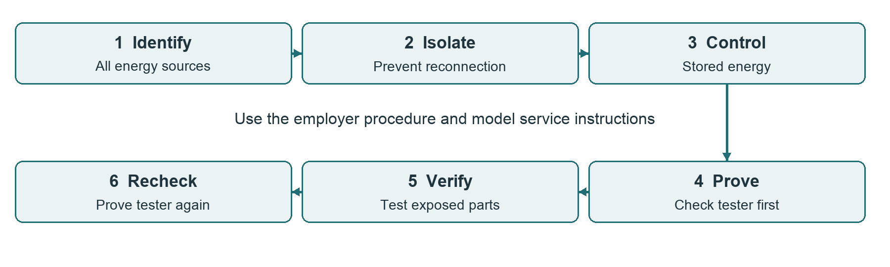
Before touching internal electrical parts, identify every supply, isolate the appliance, control stored energy, and verify the work area is de-energized. Follow the employer energy-control procedure and manufacturer instructions. [1, 2]
- Disconnect the identified supply. For cord-and-plug equipment, keep the unplugged plug under your exclusive control when that method applies. An OFF button does not isolate power.
- For hardwired equipment, use the required lockout procedure at the isolating device. A tag alone does not physically prevent reconnection and is not a casual substitute for a lock.
- A qualified person verifies absence of voltage at all relevant exposed parts, including possible backfeed. As the practice taught here, prove the tester on a suitable known source before and after the absence-of-voltage check.
A breaker label or unplugged cord is not proof that every exposed part is safe. If the tester fails its final proving check, the absence-of-voltage result is invalid. Stop and repeat the procedure with suitable equipment.
Residual capacitance
Capacitors in motor circuits, power supplies, and microwave high-voltage circuits can retain hazardous charge after disconnection. The absence of supply voltage does not prove that stored energy is gone.
Use the manufacturer’s specified discharge and verification procedure, tools, and ratings. There is no universal resistor value or waiting time that makes every capacitor safe. Do not short terminals with a screwdriver. Internal microwave work belongs with technicians specifically trained and equipped for it; GE warns that the high-voltage capacitor can remain charged after unplugging. [3]
Working live
Some diagnostic measurements require an energized circuit, but they expose the worker to electrical hazards. Only appropriately qualified personnel should perform them using a documented safe work method, suitable equipment, and required protection. In this module, learners interpret supplied voltage readings; they do not practice on exposed mains circuits. [1]
- Plan the test points, expected range, instrument ratings, and response to an unexpected reading before energizing.
- A one-hand technique does not make energized work safe: current can also travel through a hand-to-foot or hand-to-body path. Do not substitute it for isolation, training, or protective measures.
- Stop if the work area is wet, unstable, crowded, or cannot be controlled. Keep customers and pets outside the work area.
- Where the approved procedure permits, position suitable insulated clip leads while power is isolated. Re-isolate before moving them. Keep clear of moving parts and exposed conductors.
- Inspect probes and insulation; use required protective equipment and remove conductive jewelry. Never bypass an interlock to make a beginner exercise run.
GFCI behavior
A GFCI detects an imbalance between outgoing and returning current and trips at a small leakage current. It adds protection but does not replace grounding, isolation, or safe work practices.
A repeated GFCI trip may involve appliance leakage, moisture, wiring, or the protective device itself. Investigate the cause with appropriate tests. Never bypass a GFCI or remove the equipment ground to keep the appliance running.
The shock you survive
Treat any electrical shock as an incident. Stop work, prevent further exposure, obtain appropriate medical help, and report and review the event under the employer procedure. A small visible mark does not establish that an injury is minor.
Gas safety
Gas dryers and gas ranges put combustible fuel into the home. The protocols here are non-negotiable.
Detection
Separate an emergency response from controlled leak testing. Do not search for a leak when a suspected gas emergency requires evacuation. [4]
- If gas is smelled or a leak is suspected, leave immediately and warn others to leave. Do not operate switches, plugs, appliances, or phones inside.
- From a safe location outside, call the gas utility emergency line or emergency services. Do not stay inside to open windows, ventilate, or find the source.
- Do not re-enter or resume work until the responsible emergency service or utility says it is safe. Odor strength does not reliably establish the severity of a leak.
After the area has been declared safe, trained personnel may perform controlled leak testing under the applicable procedure. Use an approved, noncorrosive leak-detection solution and a detector suitable for the gas. Never use a flame. A detector reading is meaningful only within that instrument’s stated capabilities.
Pressure measurement
A manometer measures gas pressure in inches of water column. Two readings matter:
- Incoming pressure is the pressure supplied to the appliance. Compare the measured value under the specified operating condition with the exact model’s permitted inlet range.
- Manifold pressure is measured downstream of the regulator or valve at the designated port. Fuel type and model determine the specification. Values such as 3.5 inches WC for natural gas or 10 inches WC for LP are examples found on some appliances, not universal adjustment targets.
Before testing, record the specified range, units, fuel type, test port, and required load condition. Adjustments and reconnection require appropriate training and authority; complete the specified leak checks afterward.
Isolation
Locate the appliance gas shutoff before planned service and follow the applicable isolation procedure. Do not force a seized valve or operate utility-owned equipment without authority. Suspected emergency leakage calls for evacuation, not an attempt to repair the valve.
Refrigerant handling
Before opening a sealed system, identify the refrigerant and the work involved. Verify current EPA Section 608 requirements and any applicable certification, recovery, and local rules. This foundations module does not authorize sealed-system service. [5]
- Intentional venting of regulated refrigerants during service is generally prohibited. EPA lists specific refrigerant and end-use exemptions, including R-600a in household refrigerators and freezers. An environmental exemption does not make an uncontrolled flammable release safe. [5]
- Use refrigerant-compatible equipment and the recovery, handling, and documentation procedures applicable to the refrigerant and task.
- Liquid refrigerant contact can cause cold burns. Use appropriate eye and hand protection and control exposure and ventilation under the service procedure.
- R-600a is flammable. Keep ignition sources away and use the manufacturer’s hydrocarbon service procedure and suitable equipment. Removing the charge alone is not proof that hot work is safe. Hydrocarbon sealed-system work requires specialized training. [6]
Mechanical safety
- Sharp metal edges are everywhere inside an appliance cabinet. Wear gloves when reaching into unseen spaces.
- Glass shelves crack under uneven loading and break under temperature shock. Handle them with both hands and set them down on padded surfaces.
- Tipping appliances kill children and injure technicians. Strap appliances to dollies. Never leave a unit balanced on its rear wheels unattended.
- Plan appliance movement around the actual weight, route, stairs, hoses, and assistance available. Use rated handling equipment and help as needed; do not twist, catch, or balance a falling appliance.
Other hazards to check before opening the cabinet
Shut off and control water supplies before disconnecting hoses; drain residual water into a suitable container. Let hot surfaces cool. Protect against rotating parts, spring tension, and suspended assemblies. Identify an unknown hazard before proceeding.
After moving a freestanding range, verify that the required anti-tip device is properly engaged using the manufacturer’s method. Do not test stability by climbing or loading the open door. [9]
Customer property
Protecting the customer’s property is part of the job. Damage can turn a technically successful repair into a costly return visit.
- Use floor protection and suitable footwear. Shoe covers must not create a slipping hazard.
- Drop cloth or moving blanket on the floor before pulling the appliance forward.
- With the customer’s permission, photograph the appliance, work area, and existing damage. Avoid unrelated people or personal information and store records under the company policy.
- Ask permission before moving items off the top of the appliance or out of adjacent cabinets.
- Replace items where you found them when the work is complete.
The technician who leaves a kitchen cleaner than they found it is the technician who gets called back when the next appliance fails. This is not sentiment. It is business strategy.
At a call, you smell gas near a range. The customer asks you to unplug it before leaving. What do you do? At a separate call, a microwave has been unplugged overnight. Does that establish that its internal high-voltage circuit is safe?
Check your reasoning
Leave the suspected gas emergency without operating the plug or switches and call from outside. An unplugged microwave may still retain hazardous charge; refer internal work to a trained, equipped technician. Neither case is permission to improvise a test.
0.2 Tools and what they actually do
Tools are the limit of what you can know about an appliance. A meter you cannot read accurately is a meter that lies. A leak detector with a dead battery is a guess. The case for quality tools is not aesthetic. It is operational.
The digital multimeter
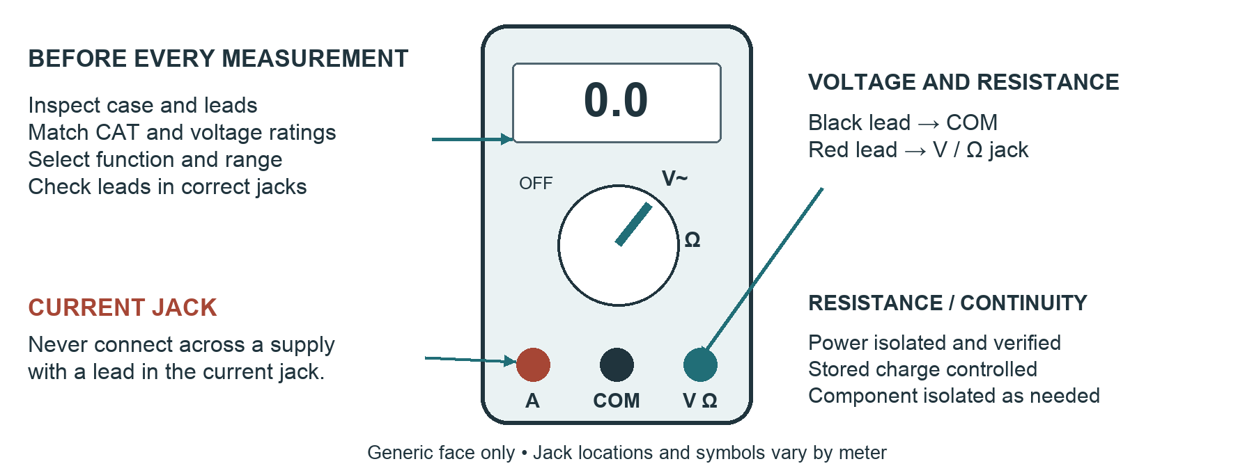
The single most important tool in your kit. A multimeter measures voltage, resistance, and continuity. Better meters add capacitance, frequency, and temperature. The capabilities most relevant to appliance work:
AC voltage
Most appliance circuits are 120V or 240V AC. Voltage measurements answer the question: is power present at this point in the circuit?
Voltage is a difference between two points. A 0 V reading may mean both points are at the same potential, a supply is absent, or the test setup is wrong. A supply-level reading across a switch can indicate an open switch. Always name both test points and the commanded operating state.
DC voltage
Control boards may contain DC supply rails for sensors and logic, often including values such as 5 V or 12 V. The correct level and reference point come from the tech sheet. Some low-voltage circuits are not isolated from mains and are unsafe to treat as touch-safe.
Resistance (ohms)
Measuring resistance answers the question: is this component within its expected operating range?
Use model specifications first. The following values illustrate interpretation; they are not universal pass-or-fail limits.
| Component or example | Expected basis | Interpretation |
|---|---|---|
| 5,400 W heater at 240 V | R = V² / P ≈ 10.7 Ω | Calculated nominal value; compare cold test with model data. |
| 700 W heater at 120 V | R ≈ 20.6 Ω | Illustration, not a universal dishwasher specification. |
| Defrost heater | Model specification | An open path needs confirmation with the heater isolated. |
| Thermal fuse | Usually near lead resistance when intact | OL supports an open fuse after the setup is verified; investigate the cause. |
| Motor or compressor | Model, temperature and winding type | Do not apply a single ohm range to every motor or inverter compressor. |
| Thermistor | Model resistance versus temperature chart | Record actual sensor temperature before judging the reading. |
For resistance, isolate and verify power, control stored charge, and disconnect at least one component lead where the service instructions require isolation from parallel paths. Record temperature and compare with the correct model specification.
Continuity
Continuity is a threshold-based resistance indication; the beep threshold varies by meter. It shows a conductive path at the meter’s small test current, not that the path can carry operating load. A component may pass cold and fail when hot or vibrating.
The phantom voltage problem
High-input-impedance meters, including professional models, may show capacitively coupled or ghost voltage on conductors near energized wiring. High impedance is useful for sensitive electronics; it is not itself a quality defect. [7]
Where suitable for the circuit and approved procedure, a low-impedance function can help distinguish coupled voltage. LoZ loads the circuit and can disturb sensitive controls. A disappearing reading is not a substitute for the complete isolation and verification procedure. [7]
The clamp meter
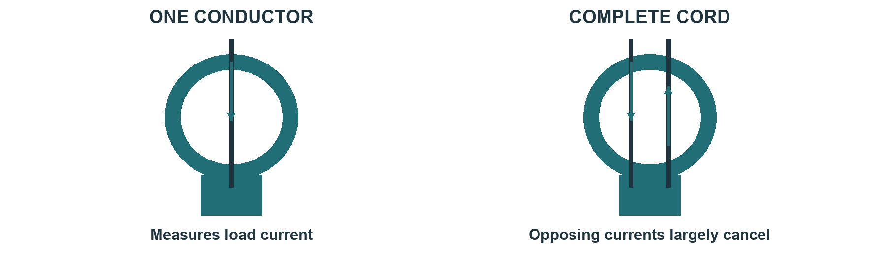
A clamp meter measures current flowing through a conductor without breaking the circuit. Open the jaws, place them around a single conductor, close them. The meter reads amps.
Clamp around a single conductor. Do not split or strip a mains cord to make this possible; use an approved method.
Use cases:
- Compressor starting current rises briefly before settling if the motor starts successfully. A motor that cannot start may draw high current until protection operates. Several electrical and mechanical causes can produce that pattern; do not diagnose a compressor from current alone.
- For an ideal resistive 5,400 W element at 240 V, current is 22.5 A. A lower reading could involve reduced voltage, a staged element, a missing parallel branch, cycling, or the wrong measurement point. A single broken series element normally becomes open; it does not simply become a half-current element.
- Compare motor current at the specified load with the model data. Abnormal current can indicate supply, starting, mechanical-load, or motor problems and requires further isolation of the cause.
The manometer
Required for any work on gas appliances. Without it, you cannot verify gas valve operation or diagnose pressure-related complaints.
Digital manometers are preferred for accuracy and ease of reading. Inches of water column is the standard unit. Carry adapters for the most common test port fittings.
Leak detectors
Refrigerant leak detection has three tiers:
- Approved bubble solution can help confirm leaks at accessible joints. Use a formulation compatible with the system and the service instructions.
- Choose an electronic detector rated for the actual refrigerant. A halogen detector suitable for R-134a may not detect a hydrocarbon such as R-600a.
- Use UV dye only when the manufacturer permits the particular dye and method. Additives and extra service access are not default first steps for a sealed system.
Combustible-gas testing requires an appropriate detector and trained interpretation. Follow the emergency response in Unit 0.1 before any planned leak-location work.
Hand tools
The minimum kit for residential appliance work:
- Magnetic nut drivers in 1/4 inch and 5/16 inch. The magnet matters. Dropping a fastener into the cabinet of a refrigerator costs you twenty minutes.
- Phillips and flathead screwdrivers, multiple sizes.
- Torx drivers in T15, T20, T25. Increasingly common on modern appliances.
- A suitable panel-release tool, used only where the service instructions identify clips and release points. Do not assume every panel pries open.
- Appliance dolly with strap. A two-wheel dolly with a built-in strap that can ratchet around a refrigerator.
- Manufacturer-approved terminals, connectors, and crimp tools appropriate to conductor size, current, temperature, and environment. Generic connectors are not interchangeable with high-temperature appliance terminals.
- Rated probes and insulated clips compatible with your meter and work procedure. Hands-free contact does not remove energized-work hazards.
The economic case for quality tools
Buy instruments for their verified ratings, needed functions, serviceability, and support. Price alone does not establish safety or accuracy. Replace damaged leads before the next measurement.
Illustrative ownership calculation: a $100 tool replaced after 2 years costs $50 per year before maintenance; a $300 tool used for 6 years also costs $50 per year. Actual life and downtime vary. Use your own service records rather than treating either life span as a guarantee.
With a disconnected training switch only, inspect the meter and leads, select continuity or resistance, and follow the instrument manual. Touch the leads together and record their resistance. Separate them and observe OL. Measure the switch in each position. Do not connect the training assembly to mains power.
| Training condition | Your reading | Meaning |
|---|---|---|
| Leads together | __________________ | Meter and lead-contact check |
| Leads apart | __________________ | Open-path indication |
| Switch closed | __________________ | Compare with lead resistance |
| Switch open | __________________ | Expected open path |
Check your reasoning
A closed switch should be near the lead resistance; an open switch should show no path. If the result changes while the leads move, investigate contact or damaged leads before diagnosing the switch. Record values, not just “good” or “bad.”
Instrument checks: verify the meter and every accessory have appropriate voltage and measurement-category ratings. Inspect insulation and test-lead continuity before work. A sound meter cannot compensate for damaged leads. [8]
0.3 Electrical fundamentals for appliance technicians
Appliance work is electrical work first and mechanical work second. The technician who understands the electrical theory diagnoses faster, repairs cleaner, and explains better. This unit covers the minimum theory required to function in the trade.
US residential electrical service
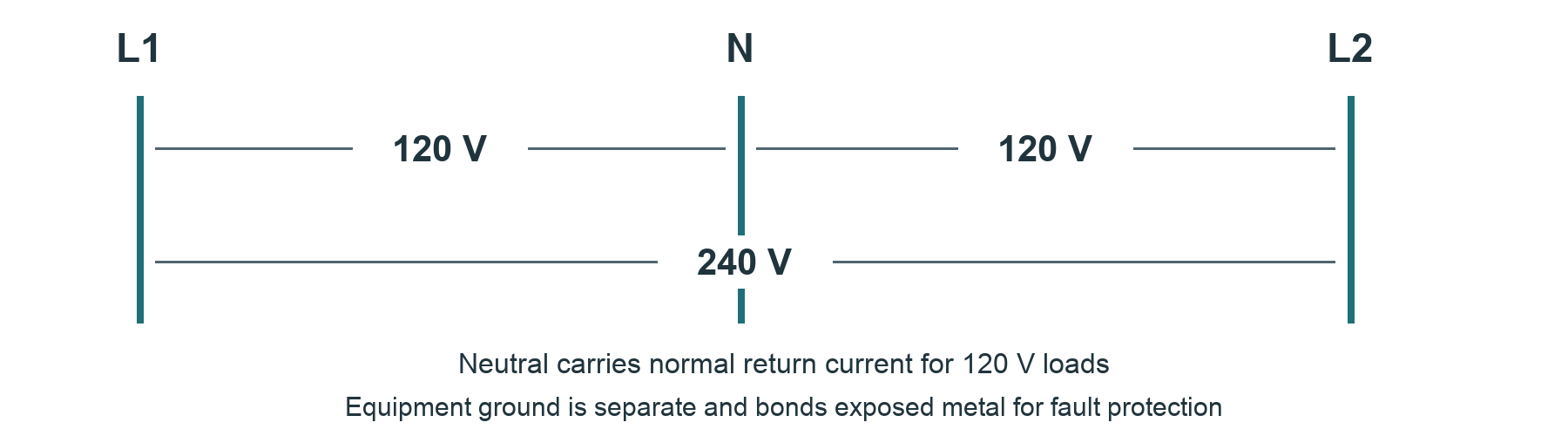
A common US residential supply is nominal 120/240 V split-phase, with two hot conductors and a center-tapped neutral. Nominal values describe the system; actual measurements and allowed tolerances must be interpreted against the appliance and supply requirements.
- Hot leg 1 to neutral: 120V
- Hot leg 2 to neutral: 120V
- Hot leg 1 to hot leg 2: 240V
This architecture has direct consequences for appliance design:
- Typical 120 V appliances use one hot conductor, neutral, and an equipment grounding conductor.
- Some 240 V loads use both hot conductors and an equipment ground without a neutral because they have no 120 V loads.
- Many electric dryers and ranges use both hot conductors, neutral, and ground for mixed 240 V and 120 V loads. Follow the model installation instructions for the actual connection; this diagram is not a guide to converting an older supply.
The dryer that tumbles but will not heat
Classic diagnostic case. The dryer drum spins, the motor runs, but no heat is produced. Possible causes include a failed heating element, a blown thermal fuse, or a lost hot leg at the breaker or outlet.
A lost supply leg can leave the 120 V motor circuit operating while the 240 V heater cannot function normally. The measured heater voltage depends on the open point and backfeed paths; it is not always 120 V.
The diagnostic plan must include verification of the required supply, including line-to-line voltage and the relevant line-to-neutral values, by qualified personnel. A running motor alone does not establish that the heating circuit has its correct supply.
Hot, neutral, and ground
- Hot conductors supply the energized circuit. Conductor colors are identification aids, not proof of voltage or function; altered appliance wiring must be checked against the schematic.
- Neutral is a normal current-carrying return conductor. In a typical premises system, neutral and equipment ground are bonded at the designated service bonding point and kept separate downstream. Do not improvise a neutral-to-chassis bond at an appliance.
- Equipment ground bonds accessible metal to the fault-return path so protective devices can operate. It must not be used as a substitute neutral. An open neutral can also make normally unexpected points hazardous.
Reversed polarity
In older homes and amateur wiring repairs, hot and neutral may be swapped at the outlet. The appliance still works (the load doesn’t care which side is hot), but the safety implications are serious. Switches and fuses on the appliance interrupt what they think is hot. With reversed polarity, they’re interrupting neutral, leaving the hot side energized inside the appliance even when the switch is off.
A plug-in tester can screen for some common receptacle wiring faults, but it cannot verify every grounding defect or prove that work is safe. Refer suspected supply wiring defects to an appropriately qualified person.
Series and parallel circuits
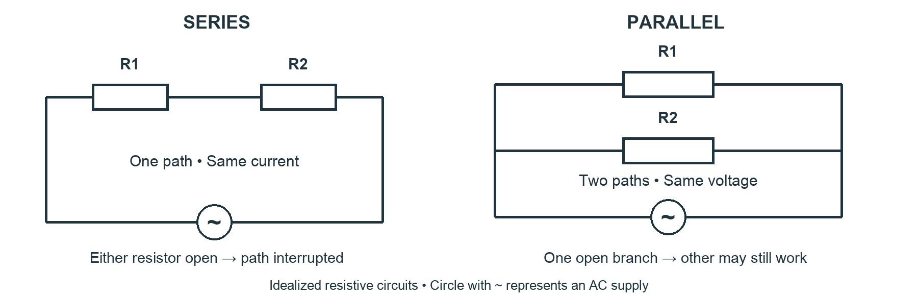
Two components wired in series share one path. Current flows through both. If either fails open, the circuit is broken.
Two components wired in parallel each have their own path. They operate independently. If one fails open, the other continues.
Why this matters
A conventional defrost heater may be in series with a temperature-operated termination device. An open terminator may be normal at a warm temperature. Compare its state and temperature with the model’s test specification before condemning it.
Some heaters have multiple switched sections or parallel branches. One open branch can reduce total heat while another operates. Other appliances use one series element; confirm the actual topology before interpreting a reduced-current complaint.
Reading the schematic correctly tells you which configuration you’re testing. Reading the schematic incorrectly leads to replacing components that work.
Reading ladder schematics
Many service diagrams use ladder-style rails and rungs; others use wiring or electronic block diagrams. A rung shows a path between supply rails through controls and loads. AC current reverses direction; trace connectivity rather than treating the diagram as a one-way flow picture.
To trace a circuit:
- Identify the function you’re diagnosing (heat, motor, controls).
- Find the rung that controls that function.
- Identify every switch, relay contact, thermostat, and fuse in series with the load.
- For the load to operate, all those switches must be closed and all fuses must be intact.
- Choose a test that separates the remaining possibilities. Begin with safe observations and isolated checks; any justified energized measurement belongs to qualified personnel.
Identify the diagram type, connector labels, component legend, and the state in which contacts are drawn. A wiring diagram shows physical connections; a schematic explains electrical relationships. Neither replaces the model service instructions.
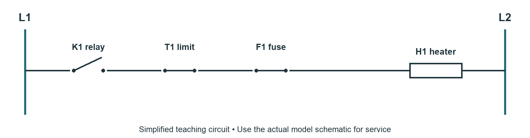
Reading the figure: K1 is the commanded relay contact, T1 a limit device, F1 a fuse, and H1 the load. The letters are teaching labels. The open contact explains the drawn state; it does not establish that the relay has failed. First ask whether the controller should be calling for heat.
Continuity testing versus voltage testing
These are the two diagnostic measurements you will perform most often. They are not interchangeable.
Continuity testing requires isolated and verified power and controlled stored energy. Low resistance or a beep indicates a path under the test conditions. OL indicates an open path or a value beyond the selected range; check setup before interpreting it.
Voltage testing measures the potential difference between named points. It is used both to verify absence of voltage and, by qualified personnel, to diagnose energized circuits. A reading must be interpreted with the supply, control state, reference point, and circuit topology.
If an isolated heater measures within specification but has no operating voltage in supplied test data, investigate the supply and control path. Resistance alone does not prove the heater performs correctly when hot.
If an isolated heater repeatedly reads OL with a proven meter and good probe contact, it has no measurable path under those test conditions. Supplied data showing full voltage across it during a heat call support an open-load diagnosis, but do not establish that every other part of the appliance is sound.
Same symptom. Different cause. Different repair. The discipline of testing both correctly is what makes a diagnostician.
Ohm’s Law applied
Voltage equals current times resistance. V = I × R.
Rearranged for the measurements you actually take in the field:
- R = V / I. In supplied test data, 240 V across a resistive element and 22 A through that element imply about 10.9 ohms at that operating condition.
- I = V / R. A nominal 10-ohm resistive load at 240 V would draw 24 A. Actual resistance may change with temperature; the supply reading must correspond to the voltage across the load.
- V = I × R. Less common in field diagnostics but useful for understanding voltage drop across long wire runs.
For a resistive load, P = V × I. At 240 V and 22 A, power is 5,280 W. Compare this with the model tolerance and operating condition before calling it acceptable. AC motors and electronic loads also involve power factor, so V × I is not automatically their real power in watts.
Worked example Predict the heater reading
A training data sheet specifies a single 5,400 W resistive element rated at 240 V. Expected nominal current is I = P / V = 5,400 / 240 = 22.5 A. Nominal resistance is R = V² / P = 57,600 / 5,400 ≈ 10.7 Ω.
If that same ideal resistance were supplied with 120 V, current would be about 11.25 A and power about 1,350 W, one quarter of rated power. This calculation does not predict every lost-leg circuit: backfeed and open paths affect the actual voltage across the heater.
Try it: a purely resistive 1,500 W load is rated at 120 V. Find current and nominal resistance. Then find power at 110 V if resistance remains constant. Answers: 12.5 A; 9.6 Ω; approximately 1,260 W. Lower voltage has a squared effect on heating power when resistance is constant.
0.4 The diagnostic method
Most failed repairs in this trade come from method failures, not knowledge failures. A technician who follows a disciplined diagnostic sequence will out-perform a technician with twice the experience who skips steps. This unit defines the sequence and the discipline.
The seven step sequence
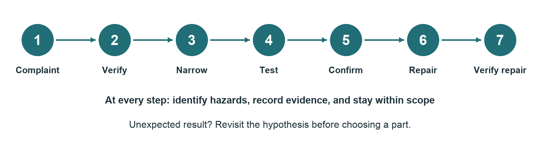
Step 1 Complaint
Capture the customer’s description verbatim. Not your interpretation of it. Not a translation into technician shorthand. Their words.
“Won’t heat” and “won’t get hot enough” are different complaints. “Doesn’t drain” and “drains slow” are different complaints. The diagnostic tree branches differently from each starting point. Substituting your version of the complaint for theirs introduces an error before you’ve even seen the appliance.
Step 2 Verify
If the safety assessment permits normal operation, reproduce the complaint with guards and panels in place. Otherwise, keep the appliance isolated and plan the next safe check from the available evidence.
A meaningful percentage of “broken” appliances are user error, environmental conditions, or transient issues that have resolved by the time you arrive. A washer that “won’t drain” may have a sock in the drain pump. A dryer that “doesn’t heat” may have a vent fully blocked at the wall cap. A refrigerator that “isn’t cooling” may have been off for an hour because the customer’s child opened the breaker panel.
Verifying the complaint also gives you the chance to observe symptoms the customer didn’t think to report. The dishwasher that “doesn’t clean well” may also be making a noise the customer assumed was normal but which points directly at a failed wash motor bearing.
Step 3 Narrow
Identify which system within the appliance is failing. Most appliances divide into several functional systems:
- Thermal (heating elements, gas burners, thermostats, fuses)
- Drive (motors, belts, transmissions, pumps)
- Water in (inlet valves, pressure switches, fill sensors)
- Water out (drain pumps, drain hoses, air gaps)
- Controls (boards, switches, sensors, user interface)
- Door and safety (interlocks, latches, lid switches)
A no-heat dryer directs attention to the heating function, but the cause may be supply, controls, airflow, or a safety device. Narrow by the failed function without prematurely assuming a failed component.
Step 4 Test
Choose the next test by safety, information gained, manufacturer guidance, and the evidence already collected. A fault code or common failure pattern provides a hypothesis, not a part order.
For a no-heat electric dryer, first establish the settings, model-specific circuit, and required supply. Then choose isolated tests that distinguish the control path, safety devices, and heater. The effect of a thermal fuse differs by model and where it appears in the circuit.
For refrigerator frost-up, inspect the documented frost pattern and airflow, then follow the model defrost diagnostic procedure. A temperature-operated device must be tested in its specified temperature state. There is no universal component failure ranking across refrigerators.
Manufacturer bulletins and your service history can refine priorities, but should never overrule contradictory measurements or a safer, more informative test.
Step 5 Confirm
Verify your diagnosis with a second measurement before ordering parts.
Repeat the isolated measurement after checking the meter, lead contact, temperature, and connection points. Look for independent supporting evidence where available; an electrical failure need not be visibly burned. If a compressor is suspected of a winding-to-shell fault, keep it isolated and follow the approved insulation-test procedure. Do not energize it or add a hard-start kit to confirm a ground fault.
Confirmation means the evidence survives a reasonable attempt to disprove the diagnosis. Record what failed, the specification, the measured result, and what competing cause you ruled out.
Step 6 Repair
Replace the failed component. While you have the unit open, inspect adjacent components for related failure or wear that suggests imminent failure.
An open thermal protective device requires investigation of overheating and the model-specific causes, such as airflow restriction or control faults. Replacing it alone may leave the underlying problem. Never bypass or fit a higher-rated safety device.
This is where the work crosses from technician to diagnostician. The component replacement is mechanical. Identifying why the component failed is the value you provide.
Step 7 Verify the repair
Complete the manufacturer’s post-repair checks and a suitable operational test that covers the original symptom. Some conditions require a full cycle or extended temperature stabilization. Record the conditions and duration; if verification is incomplete, state what remains and arrange follow-up.
Reinstall guards, panels, grounding connections, hoses, and required restraints before handoff. Show the customer the verified operating result and explain any limit to what has been tested.
Why technicians skip steps
Each step costs time. The pressure to move to the next call is real. The temptation to assume rather than verify is constant.
Step 2 (verify) is skipped because the customer already told you the symptom. The cost is occasionally diagnosing a problem that isn’t there.
Step 5 (confirm) is skipped because experienced technicians “know” the answer. The cost is occasionally being wrong with high confidence.
Step 7 (verify the repair) is skipped because the noise stopped and the customer is happy. The cost is the callback when the secondary failure surfaces a week later.
Differential diagnosis
Two or more conditions producing the same symptom. The diagnostician’s job is to enumerate the possibilities and design tests that distinguish between them.
Example: a refrigerator that won’t cool. Possible causes:
- Sealed system leak (low refrigerant, partial cooling, eventual no cooling)
- Failed compressor (no cooling, audible click on attempted start, locked rotor or open winding)
- Failed evaporator fan (poor air distribution despite cooling at the evaporator)
- Condenser airflow problem (poor heat rejection and possible thermal protection operation, depending on the design)
- Defrost system stuck on (thawed evaporator, no cold air, looks like no cooling)
- Failed control board (no command to compressor, no cooling)
- Failed thermistor (incorrect temperature reading, board doesn’t call for cooling)
Observations such as compressor sound, fan operation, frost pattern, and measured temperatures help prioritize hypotheses. They do not conclusively eliminate causes on their own. Take measurements without contacting moving parts or unsafe hot surfaces.
Confirmation bias
The mental tendency to test only what would confirm what you already expect. The dryer technician who has seen three failed thermal fuses this week tests for a thermal fuse on the fourth call without considering other possibilities.
Familiarity can make a hypothesis useful, but confirmation bias hides alternatives. Look for an observation that would change your mind before ordering a part.
Two protective practices:
- Force yourself to articulate at least three possible causes before testing the first one.
- After diagnosis, ask: “What would I test if I were wrong about this?” If the answer is “I haven’t ruled out X,” rule out X before ordering the part.
Worked case The dryer tumbles but does not heat
Illustrative training case. Complaint: “The drum turns, but the clothes stay cold.” Settings call for heat. The exact model diagram shows a single heater in series with a control contact, limit, and fuse. Supplied qualified-technician data confirm the required supply. With power isolated and stored energy controlled, the heater reads 10.8 Ω, the limit is closed in its specified test state, and the isolated fuse reads OL twice. Leads together read 0.2 Ω.
Reasoning: the confirmed open fuse interrupts this model’s heater path. The heater reading alone does not prove performance when hot. Inspect the model’s overheating causes before specifying a repair. Suppose inspection also documents a crushed exhaust connection; that is a plausible contributor to be corrected and verified, not permission to bypass the fuse.
Decision: propose the correct safety device and correction of the documented restriction, obtain authorization, then complete the specified airflow and heating checks. If the full exhaust path cannot be evaluated, state that limitation and arrange the required work before declaring the appliance ready for normal use.
Worked case The washer will not drain
Illustrative training case. The customer reports standing water after the cycle. Possible causes include a blocked hose or filter, a jammed or failed pump, and a missing control command. An error code identifies the drain complaint but does not identify which cause is present.
Begin with model instructions, safe isolation, and controlled water removal. Suppose the accessible filter contains a small garment and the drain path can be cleared safely. Reassemble and perform the specified fill-and-drain leak checks. Successful draining after clearing the obstruction supports the repair; replacing the pump without that inspection would not have been justified.
Practice: for each case, write one finding that would change the diagnosis. Examples: the fuse measures closed when properly isolated, or the washer still will not drain after the path is confirmed clear. Explain the next test instead of naming the next part.
0.5 Customer interaction baseline
Customer interaction in this trade is treated as a soft skill in most training programs. That treatment is incorrect. The intake call is the first diagnostic step. The on-site protocol determines the technician’s effective working environment. The handoff conversation determines whether the customer pays the invoice and calls back when the next appliance fails. Each of these is a technical process with measurable outcomes.
The intake call
Whether you take the call yourself or it’s handled by a dispatcher, the data captured determines the quality of the service call. The required intake fields:
- Appliance type (refrigerator, washer, dryer, dishwasher) and configuration (top load or front load, gas or electric, French door or top freezer).
- Brand.
- Model number, read off the rating plate. Always ask. The customer often doesn’t know it. Walk them through finding it.
- Serial number when possible. Useful for warranty lookups and for identifying production runs with known issues.
- Complaint, in the customer’s own words. Write it down verbatim.
- When the issue started. What changed before it started (a move, a power outage, a thunderstorm, a recent purchase).
- Has anyone worked on it before. If yes, what did they do.
- Address. Access conditions (apartment building, basement, crawl space, gated community). Pets in the home.
- Diagnostic fee, stated explicitly. The customer must hear this number, agree to it, and be reminded of it on arrival.
The intake call is not a sales call. It is an information-gathering procedure that determines the quality of every step that follows. Treat it that way.
On site protocol
Arrival
- Arrive within the stated window. If you will be late, call from the previous appointment, not from the customer’s driveway.
- Knock at the front door. Identify yourself by name and company. Show ID if your company issues it.
- Confirm the appliance and the complaint with the customer before beginning work. The phone description and the actual situation sometimes differ.
Preparation
- Protect flooring with materials and footwear that preserve grip and safe movement.
- Drop cloth or moving blanket on the floor in front of the appliance, before pulling it forward.
- With permission, photograph relevant appliance and work-area conditions, including existing damage. Keep the record focused on the service need.
- Ask permission before moving items off the top of the appliance, out of adjacent cabinets, or off the floor.
During the work
- Keep the customer informed at major decision points. “I’ve found the problem. It’s the inlet valve. Before I order the part, can I show you what I found?”
- Maintain a clean work area. Tools on a tool mat or in the toolbox, not on the customer’s countertop. Replaced parts in a bag or tray, not on the floor.
- If the work expands beyond the original scope, stop. Call the customer. Re-quote. Get authorization before continuing.
Diagnostic communication
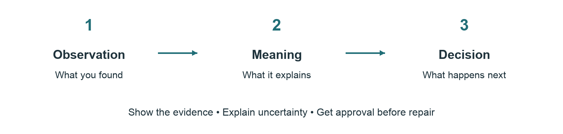
After you’ve diagnosed but before you’ve quoted, explain what you found in language the customer can use. The framework:
- State what’s failed, in plain language. “The thermal fuse on the dryer is blown. It’s a safety device that opens when the dryer overheats.”
- State the likely cause only to the degree your evidence supports it. “The exhaust path is restricted, which can cause overheating. We need to address it as part of the repair.”
- State the proposed work and any remaining uncertainty. “I propose replacing the confirmed open safety device and correcting the airflow restriction, then performing the model’s operational checks.”
- State the cost. Parts, labor, total. In writing if possible.
- State the alternative and whether the appliance can be used safely. Do not promise partial operation when a safety fault remains unresolved.
Show the relevant measurement or photo where useful. Many failed parts look normal; visible damage is not required. Explain what the evidence establishes without inviting the customer near exposed hazards.
Pricing transparency
- State the company’s diagnostic fee, when it is payable, and whether it is credited toward repair. Confirm the customer’s agreement before beginning chargeable work.
- The repair quote is firm before you begin the repair work. Surprise charges destroy trust faster than any other technician behavior.
- If scope expands during the repair, stop work, call the customer, re-quote, and get authorization. “While I had the back off, I noticed X. It will add Y to the cost. Do you want me to address it now or leave it for later?” That conversation preserves the relationship. Discovering the additional charge on the invoice destroys it.
The handoff
- Provide a written work order with the diagnosis, evidence, authorized work, parts, total charges, and the applicable written warranty terms. Do not invent warranty coverage.
- Demonstrate normal operation using the documented test results. A warm door alone does not verify dryer performance, airflow, or control cycling.
- Explain which specific symptoms require follow-up, how to contact the shop, and any documented use restrictions. State the actual warranty period and terms.
- Collect payment according to the agreed terms and provide a receipt. Confirm arrangements for any return visit.
- Departure. Leave the workspace as clean as you found it, or cleaner. Replace items where they were. Take the old parts with you unless the customer requests them.
The repeat customer mathematics
Customer acquisition and return visits both consume money and time. Track your actual acquisition cost, callback cost, repeat bookings, and referrals; there is no single reliable dollar range for every shop.
The customer interaction practices in this unit are not optional polish. They are the mechanism that converts a single service call into a multi-call relationship and a referral pipeline. The technician who treats every interaction as a one-time transaction pays the new-customer acquisition cost on every call. The technician who treats every interaction as the first call of a long relationship pays it once and benefits for years.
What to write down
After the call, before you leave the driveway, capture in your notes:
- Customer name, address, phone.
- Appliance, brand, model, serial.
- Complaint as stated.
- Diagnosis.
- Repair performed, parts used, parts ordered if return visit needed.
- Record service-relevant preferences and access needs with appropriate care. Avoid unrelated personal judgments or unnecessary sensitive information.
- Anything notable about the appliance (other components showing wear, anticipated future failures).
This record is the asset that makes you a better technician on the next call to the same customer. It is also the basis for the proactive maintenance offering you may build later in your career.
You find a restricted dryer exhaust connection and an open safety device. Give a 30-second explanation with the evidence, proposed work, uncertainty, and next approval. Avoid saying that every other part is fine or guaranteeing a result before verification.
Example: “This safety device has no electrical path when tested in isolation. I also found a crushed exhaust connection, which can contribute to overheating. I propose replacing the specified device, correcting the restriction, and checking operation and airflow. The written quote lists the work and cost. Any additional finding would need your approval before I proceed.”
Module 0 Assessment
This edition includes the 30-question written examination, three original schematic-reading exercises, answer explanations, and a scoring rubric. Complete the assessments before reading the answers. Written and practical scores must each reach 80 percent for course progression.
Written examination
The written assessment in the assessment section contains thirty questions covering:
- Electrical safety protocols (lockout-tagout, residual capacitance, working-live procedure).
- Gas safety, pressure specifications, leak detection, and evacuation for a suspected gas emergency.
- Tool selection (which instrument for which measurement).
- US residential electrical service architecture (split phase, hot-neutral-ground, polarity).
- Series versus parallel circuit identification.
- Continuity versus voltage testing (when to use each).
- Ohm’s Law calculations (resistance, current, voltage, power).
- The seven-step diagnostic sequence (definitions and reasoning).
- Customer interaction protocols (intake, on-site, handoff).
Practical exercise schematic reading
Three original, simplified teaching schematics are included in the practical assessment. They model circuit reasoning and are not copied from manufacturer service manuals or substitutes for them. For each schematic:
- Identify the circuit responsible for the stated function (heat, drive, drain).
- List every component in series with the load.
- Use the supplied symptom and readings to choose a defensible, safe diagnostic sequence.
- Explain in writing why this sequence is correct.
Passing standard
Score at least 24 of 30 on the written examination and 12 of 15 on the practical assessment. Any unsafe proposed action requires correction before progression. As stated in the course policy, a student who fails either component may retake it once after a 14-day review period at no additional cost.
Progression
After meeting the course progression requirements, continue to Module 1 Refrigerators. Keep the field worksheets and revisit the relevant foundation whenever a later diagnosis becomes difficult.
Written assessment: 1–10
Complete all 30 questions before checking the answers. Each question is worth one point. Choose one answer unless a calculation or brief response is requested. For a two-part prompt, both parts must be correct for the point. Use supplied data; do not take live measurements. Passing score: 24 of 30.
1. The appliance OFF button is pressed. Is that sufficient isolation?
A Yes, if the display is dark. B No; isolate the supply and verify.
2. You smell gas on arrival. What is the first response?
A Unplug the range. B Leave and call from outside. C Search with a detector.
3. A microwave was unplugged overnight. What internal hazard can remain?
Give a brief answer.
Answer: ____________________________________________________________
4. Before a resistance test, name two required conditions.
State the energy condition and how parallel paths are handled.
Answer: ____________________________________________________________
5. A tester fails the proving check after an absence-of-voltage test. What does that mean?
A The result remains valid. B The result must be treated as invalid and rechecked safely.
6. For voltage or resistance, the black lead goes to COM and the red lead goes to which jack?
A The marked V / Ω jack. B The current jack. C Any open jack.
7. Can a continuity beep prove a connection carries its normal operating load?
Answer yes or no and state why.
Answer: ____________________________________________________________
8. To measure load current with a clamp meter, clamp around what?
A A single conductor using an approved access method. B The complete supply cord.
9. Are ghost voltages unique to inexpensive meters?
Answer yes or no and identify the relevant meter characteristic.
Answer: ____________________________________________________________
10. Why is LoZ not the default choice for every sensor circuit?
Give a brief answer.
Answer: ____________________________________________________________
Written assessment: 11–20
11. In nominal 120/240 V split-phase service, what is L1-to-neutral voltage?
A 60 V. B 120 V. C 240 V.
12. In that same system, what is L1-to-L2 voltage?
A 0 V. B 120 V. C 240 V.
13. What is the normal role of the equipment grounding conductor?
A Carry the normal heater return current. B Provide fault protection by bonding exposed metal.
Answer: ____________________________________________________________
14. Two devices are in series. One becomes open. What happens to current through that path?
Give a brief answer.
Answer: ____________________________________________________________
15. Two resistive loads are in parallel. One branch becomes open. Must the other stop?
Answer yes or no, assuming its supply and control remain available.
Answer: ____________________________________________________________
16. Calculate current for an ideal 5,400 W resistive heater at 240 V.
Show the formula and unit.
Answer: ____________________________________________________________
17. Calculate nominal resistance for that same heater.
Round to one decimal place and include the unit.
Answer: ____________________________________________________________
18. Calculate heating power for a resistive load with 120 V across it and 10 A through it.
Show the formula and unit.
Answer: ____________________________________________________________
19. A dryer tumbles normally. Does that prove the heater has the required 240 V supply?
Answer yes or no and give the reason.
Answer: ____________________________________________________________
20. A defrost terminator is open while warm. Is failure established?
Answer yes or no and name the missing comparison.
Answer: ____________________________________________________________
Written assessment: 21–30
21. Put the seven diagnostic steps in order.
Use: Repair; Complaint; Confirm; Verify repair; Narrow; Verify complaint; Test.
Answer: ____________________________________________________________
22. What should determine the next diagnostic test?
A The most familiar part. B Safety, evidence, information gained and manufacturer guidance.
23. An appliance displays a drain error. Does that alone justify ordering a pump?
Answer yes or no and give one alternative cause.
Answer: ____________________________________________________________
24. A compressor is suspected of a winding-to-shell fault. What should you do?
A Add a hard-start kit and energize it. B Keep it isolated and follow the approved confirmation procedure.
25. Why investigate an open thermal fuse’s cause before closing the job?
Give a brief answer.
Answer: ____________________________________________________________
26. Where should the permitted gas pressure and test conditions come from?
A A generic value remembered from class. B The exact model and fuel specifications.
27. Does an EPA venting exemption make an uncontrolled R-600a release safe?
Answer yes or no and state the physical hazard.
Answer: ____________________________________________________________
28. A new problem would increase the repair price. What happens before the extra work?
Give a brief answer.
Answer: ____________________________________________________________
29. Name two records that make a meter reading useful for diagnosis.
Choose two: test points; operating state; units and function; specification; isolated or energized condition.
Answer: ____________________________________________________________
30. The symptom has not returned during a short test, but a full verification is still required. What should the work order say?
Give a brief answer.
Answer: ____________________________________________________________
Practical assessment instructions
Use the three supplied teaching schematics and data on the following pages. No real appliance testing is required. Treat the readings as observations already obtained through a qualified technician’s safe procedure. The diagrams deliberately omit unrelated loads and electronics.
For each case, identify the target path, use the readings to support a provisional diagnosis, state a safe confirmation, and explain verification. Do not assume a device is failed because its symbol is drawn open or closed. Any part selection must follow the actual model specification.
Scoring for each case
| Criterion | Points | Credit requires |
|---|---|---|
| Circuit identification | 1 | Names the load and all labeled series devices. |
| Evidence and interpretation | 2 | One point for the likely location; one for using the readings and acknowledging a limit. |
| Safe confirmation | 1 | A test or check that distinguishes the remaining cause without bypassing protection or unjustified live work. |
| Repair verification | 1 | A relevant operational check and a documented outcome or limitation. |
Total: 15 points. Passing: 12 points. A proposed unsafe act must be corrected before progression even if the numerical score is passing. Examples include bypassing a fuse, resistance testing on an energized circuit, or energizing a suspected ground-faulted motor.
Response format
- Target load and series devices.
- Most likely fault and supporting data.
- What the data do not establish.
- Safe confirmation or next test.
- Repair and operational verification.
Before submitting
- Name both ends of every measurement and its units.
- Use the case’s stated operating condition rather than assuming one.
- Separate “the path is open” from “this is why it opened.”
- Do not recommend a part until your evidence supports that part.
Practical case A: Heater path
All contacts are drawn closed for path tracing. Use the supplied observations to identify the actual open path.
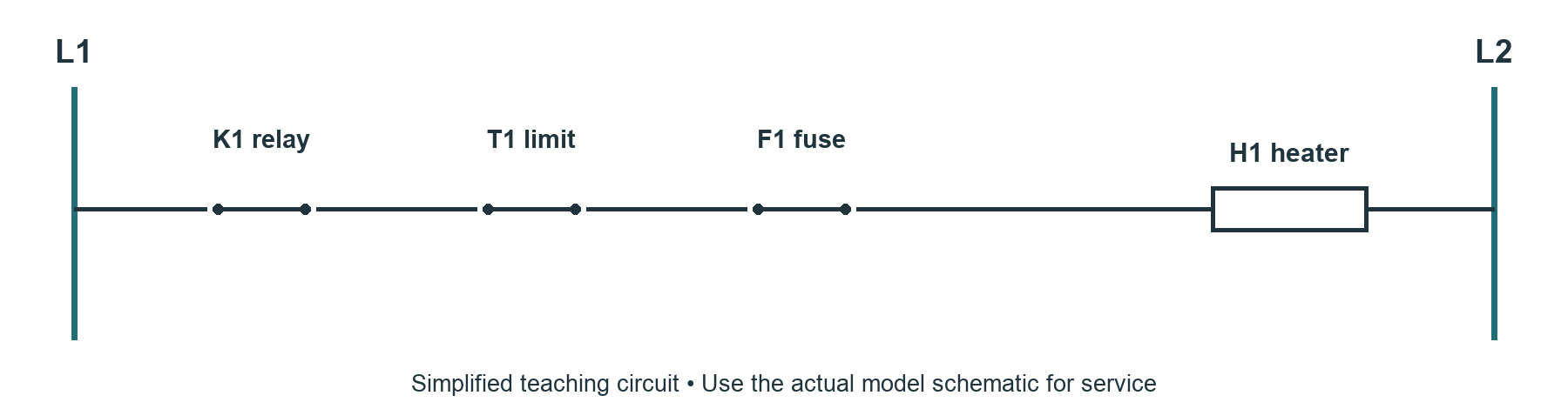
The heater does not operate during a valid heat call. Supplied data confirm nominal 240 V between L1 and L2. With power isolated and each component measured independently: K1 closes when checked under the specified service procedure, T1 is closed in the specified state, F1 reads OL twice, and H1 reads 10.8 Ω. Meter leads together read 0.2 Ω.
1 Target load and every series device
______________________________________________________________________________
2 Provisional diagnosis and supporting measurements
______________________________________________________________________________
______________________________________________________________________________
3 Limit of the evidence
______________________________________________________________________________
4 Safe confirmation or next check
______________________________________________________________________________
5 Repair verification and documentation
______________________________________________________________________________
______________________________________________________________________________
Practical case B: Drive path
Consider the switch, its actuator and the test setup before choosing a replacement. Correct winding resistance does not prove that a motor can run under load.
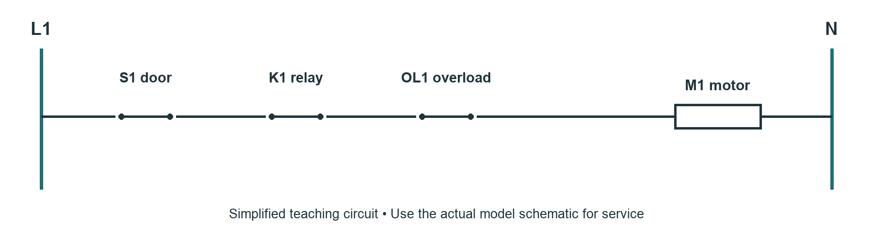
The motor will not run with the door closed and a valid run command. Supplied data confirm nominal 120 V between L1 and N. Isolated tests show S1 remains OL with the door correctly latched and the actuator in its specified position. K1 closes under the specified check; OL1 is closed. M1 winding resistance matches the model data.
1 Target load and every series device
______________________________________________________________________________
2 Provisional diagnosis and supporting measurements
______________________________________________________________________________
______________________________________________________________________________
3 Limit of the evidence
______________________________________________________________________________
4 Safe confirmation or next check
______________________________________________________________________________
5 Repair verification and documentation
______________________________________________________________________________
______________________________________________________________________________
Practical case C: Drain path
The voltage reading was taken before isolation. All resistance testing was performed afterward with the pump disconnected.
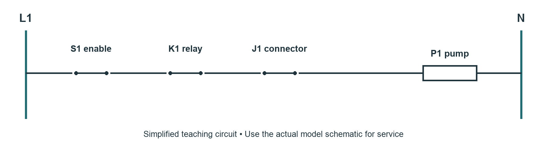
The pump is silent during a valid drain command. Supplied qualified-technician readings show nominal 120 V directly across the P1 terminals. After safe isolation, the disconnected pump winding reads OL twice with the meter proven before and after. S1, K1 and J1 have no documented defect. The water path has not yet been inspected.
1 Target load and every series device
______________________________________________________________________________
2 Provisional diagnosis and supporting measurements
______________________________________________________________________________
______________________________________________________________________________
3 Limit of the evidence
______________________________________________________________________________
4 Safe confirmation or next check
______________________________________________________________________________
5 Repair verification and documentation
______________________________________________________________________________
______________________________________________________________________________
Service worksheet: Intake and test plan
Copy this page for practice or a service record. Capture only information needed for the job and keep it under the company’s record-retention policy.
Date and work order number
______________________________________________________________________________
Customer contact and service address
______________________________________________________________________________
Appliance type Brand Model Serial Fuel or refrigerant if relevant
______________________________________________________________________________
Complaint in the customer’s exact words and when it occurs
______________________________________________________________________________
______________________________________________________________________________
Recent changes Prior repairs Access constraints Relevant permissions
______________________________________________________________________________
Diagnostic fee and terms explained Customer authorization recorded
______________________________________________________________________________
Before testing
- ☐ Hazards identified ☐ Scope and qualifications checked ☐ Work area protected
- ☐ Correct model instructions obtained ☐ Energy-control procedure established
| Possible cause | Evidence expected | Safest useful check |
|---|---|---|
| 1 __________________ | __________________ | __________________ |
| 2 __________________ | __________________ | __________________ |
| 3 __________________ | __________________ | __________________ |
Stop-work condition or referral needed
______________________________________________________________________________
Service worksheet: Evidence and closeout
Date Work order Appliance model
______________________________________________________________________________
| Test points and function | State and specification | Result and implication |
|---|---|---|
| __________________ __________________ | __________________ __________________ | __________________ __________________ |
| __________________ __________________ | __________________ __________________ | __________________ __________________ |
| __________________ __________________ | __________________ __________________ | __________________ __________________ |
Diagnosis and confirmation Competing cause ruled out
______________________________________________________________________________
______________________________________________________________________________
Proposed repair Parts Labor Total Applicable warranty terms
______________________________________________________________________________
Customer approval and any approved change of scope
______________________________________________________________________________
Work completed and underlying cause addressed
______________________________________________________________________________
Verification conditions Cycle or duration Measured outcome Remaining limits
______________________________________________________________________________
______________________________________________________________________________
- ☐ Guards and panels installed ☐ Grounding connections restored
- ☐ Water or gas connections checked as applicable ☐ Required restraints engaged
- ☐ Work area restored ☐ Use restrictions and follow-up explained ☐ Receipt provided
Customer handoff Payment per agreed terms Follow-up owner and timing
______________________________________________________________________________
Answers and explanations
Use this section after attempting the assessments. Give one point per completely correct written answer. Equivalent technically sound wording is acceptable. Revisit the named unit when an answer is uncertain.
- B. An OFF control is not supply isolation; verify the de-energized condition. Unit 0.1.
- B. Leave without operating electrical equipment and call from a safe location outside. Unit 0.1.
- Stored high-voltage charge in the capacitor can remain after unplugging. Internal microwave work needs specific training and equipment. Unit 0.1.
- Power must be isolated and verified, with stored energy controlled; isolate the component from parallel paths as required by the test. Unit 0.2.
- B. The failed proving check invalidates the result. Stop and repeat safely using suitable test equipment. Unit 0.1.
- A. Use the meter’s marked V / Ω input and COM for these functions. Locations vary by model. Unit 0.2.
- No. The beep establishes a path at low test current; it does not prove performance under load. Unit 0.2.
- A. A single conductor. Supply and return currents inside a complete cord largely cancel. Unit 0.2.
- No. High input impedance allows coupled voltage to be displayed, including by quality professional meters. Unit 0.2.
- LoZ loads the circuit and may disturb sensitive electronics or change the reading. Unit 0.2.
- B. Nominal 120 V. The actual measurement must be interpreted in context. Unit 0.3.
- C. Nominal 240 V between opposite hot legs. Unit 0.3.
- B. Bond exposed metal into the fault-return path; it is not the normal neutral return. Unit 0.3.
- Current stops through that series path because the conductive route is interrupted. Unit 0.3.
- No. The other parallel branch can continue if its own path, supply and control remain available. Unit 0.3.
- I = P / V = 5,400 / 240 = 22.5 A. Unit 0.3.
- R = V² / P = 57,600 / 5,400 ≈ 10.7 Ω. Unit 0.3.
- P = V × I = 120 × 10 = 1,200 W for the specified resistive load. Unit 0.3.
- No. A 120 V motor circuit can work while the heater’s required line-to-line supply is unavailable. Unit 0.3.
- No. Compare the terminator’s state at its measured temperature with the model specification. Unit 0.3.
- Complaint → Verify complaint → Narrow → Test → Confirm → Repair → Verify repair. Unit 0.4.
- B. Select tests that are safe and separate plausible causes using model guidance and current evidence. Unit 0.4.
- No. A blocked hose or filter, missing control command, or other drain-path issue can produce the complaint. Unit 0.4.
- B. Keep it isolated and use the approved confirmation procedure; do not energize a suspected ground fault. Unit 0.4.
- The overheating or other underlying cause may remain and cause another failure or unsafe operation. Unit 0.4.
- B. Use the exact model, fuel, pressure range, port and operating-condition specification. Unit 0.1.
- No. R-600a is flammable; the environmental exemption does not remove fire or explosion hazards. Unit 0.1.
- Stop, explain the changed scope and price, and obtain customer authorization before the extra work. Unit 0.5.
- Any two listed records earn the point; a useful full record includes all of them and the actual reading. Units 0.2 and 0.5.
- State exactly what was tested, for how long, what remains unverified, and the follow-up or use restriction required. Units 0.4 and 0.5.
Practical assessment model reasoning
Case A Heater path
The path is L1 → K1 → T1 → F1 → H1 → L2. F1 is the confirmed open series device, supported by repeated isolated OL readings and the meter check. The supply and H1 readings do not identify why F1 opened or prove every control performs under load.
Confirm against the correct fuse specification and inspect the model-specific overheating causes, including airflow and control operation. Replace only with the specified part after authorization and correction of the cause. Verify the prescribed heating and airflow behavior with the cabinet restored; document results and any remaining restriction or limit.
Case B Drive path
The path is L1 → S1 → K1 → OL1 → M1 → N. The open S1 path prevents operation in this simplified circuit. Check its isolated terminals, actuator travel and latch alignment under the specified conditions before concluding that the switch itself needs replacement. A sound winding reading does not establish motor performance.
Correct the confirmed switch or actuation defect using the model procedure, without bypassing the interlock. Restore guards and verify normal start, operation, and door-interlock behavior through the approved test. Document whether the original no-run condition is resolved.
Case C Drain path
The path is L1 → S1 → K1 → J1 → P1 → N. The repeated isolated OL reading supports an open pump winding; the supplied voltage across P1 during a drain command supports that conclusion. The data do not prove the water path is clear or identify why the winding opened.
Confirm probe contact and the model’s winding test specification. Inspect the accessible drain path safely, controlling standing water and any sharp debris. After authorized repair and reassembly, perform the specified fill, drain and leak checks. Record drain performance and any condition still requiring attention.
Record your result
Written score: ______ / 30 Practical score: ______ / 15
Unsafe proposed actions corrected: ______________________________________
Units to review: ______________________________________________________
Review completed on: ________________ Retake eligible on: ________________
Course policy retains one retake after a 14-day review period at no additional cost. Course progression is separate from authorization to perform hazardous work independently.
Quick reference and terminology
| Term | Meaning in this module |
|---|---|
| Open circuit | An interrupted conductive path; distinguish a failed device from one correctly open in its operating state. |
| Short circuit | An unintended low-resistance connection. “Short” is not a synonym for every electrical failure. |
| Ground fault | An unintended connection to grounded metal or ground. Keep suspect equipment isolated. |
| Continuity | A meter indication of a conductive path below its threshold. Not proof of load capability. |
| OL | Open path or over-range indication, depending on function and instrument. |
| Voltage drop | Potential difference across a component or connection while conditions are specified. |
| Interlock | A device or control that prevents operation unless a required condition is met. |
| Thermistor | A temperature-dependent resistor; compare resistance at a known temperature with model data. |
| Inrush | A brief starting-current transient; interpret with the operating condition. |
| Ladder schematic | A logical representation of paths between supply rails. |
| Root cause | The condition that produced the observed failure; may require more evidence than the failed part itself. |
Calculations for resistive examples
V = I × R I = V / R R = V / I
P = V × I P = V² / R R = V² / P
V in volts I in amperes R in ohms P in watts
Use model specifications and the relevant operating temperature. For AC motors and electronic loads, apparent power in volt-amperes and real power in watts can differ.
Sources and further study
These sources support the revised safety and instrument guidance. They are learning references, not a substitute for the exact appliance service manual, workplace procedure, or applicable local requirement. Web guidance checked September 2026.
Electrical work practices, de-energizing, verification and qualified-person requirements.
Hazardous-energy control, lockout and cord-and-plug scope provisions.
[3] GE Appliances Microwave Runs But Does Not Heat
Warning about retained high-voltage capacitor charge after unplugging.
[4] National Grid Gas Emergencies
Evacuation and contacting help from outside when a leak is suspected.
[5] US EPA Prohibition on Venting Refrigerants
Venting prohibition and refrigerant-specific end-use exemptions.
[6] Secop Application Guideline R600a and R290
Specialized training and equipment considerations for flammable refrigerants.
[7] Fluke Dual Impedance Digital Multimeters
High impedance, ghost voltage and limitations of low-impedance measurement.
[8] Fluke How to Test Multimeter Test Leads
Lead inspection, continuity and appropriate instrument and accessory ratings.
[9] CPSC Range Tipover Safety Alert
Manufacturer anti-tip hardware and range stability.
Illustrations and practice cases
The opening appliance illustration was generated for this edition. All technical figures are original teaching diagrams. The case readings are invented for practice and are labeled as such; they are not manufacturer specifications or records of customer repairs.
Continue with the actual meter manual and model service sheets under qualified supervision. Use the worksheets to make your reasoning and verification visible on every practice case.
Ready for the other five modules?
The complete AR-101 course adds Washers, Dishwashers, Ranges, the Business of Repair, and Sealed Systems with EPA 608 exam prep, plus assessments and apprentice track eligibility. Prefer a quick reference for the truck? Try the Field Diagnostic Kit.
Service Trade Institute · AR-101 Module 0 Foundations · Built from field practice at Appliance Intervention (Mechanicsburg, PA).
Educational use only. This module does not confer electrical, gas, refrigerant, or manufacturer authorization. Follow local code, employer procedures, and manufacturer instructions.